Hsv controllers, 23 hsv210 controller—rear view, 20 fibre channel switch basic troubleshooting – HP 4000.6000.8000 Enterprise Virtual Arrays User Manual
Page 68
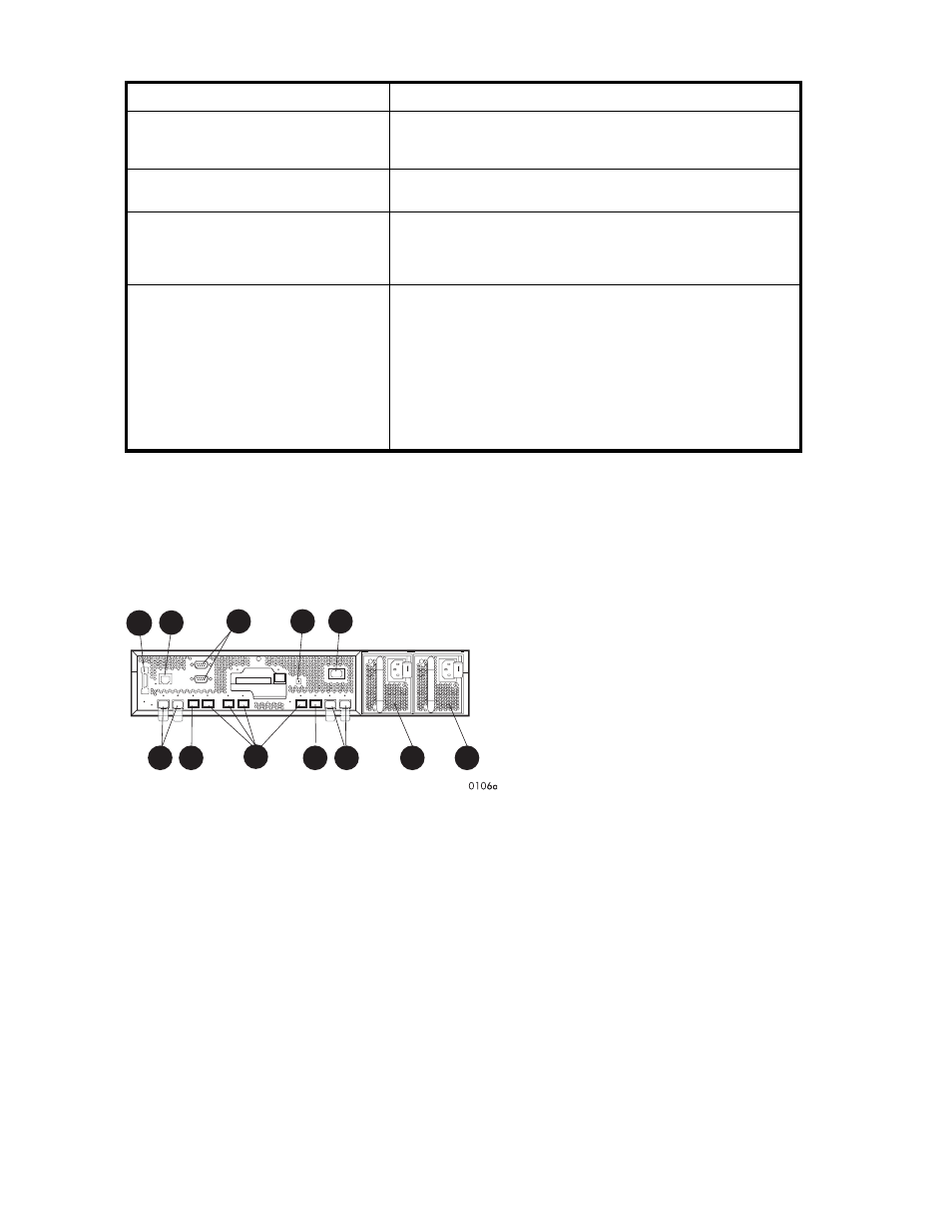
Table 20 Fibre Channel switch basic troubleshooting
Problem
Recommended action
SFPs are installed in ports but no
indicators are lit.
1. Verify that the power cord is firmly seated in the switch and
is connected to the power outlet.2. Check the power indicator
to verify that the switch is on.
SFP is installed, but the Port Bypassed
indicator is lit.
Re-seat the SFP. If the same condition occurs, the SFP is probably
faulty and should be replaced.
SFP is installed, but the SFP status
indicator and the Port Bypassed indicator
are lit.
This condition indicates that the switch is not receiving a valid
Fibre Channel signal or that the switch is receiving an LIP.1. Ensure
that the switch is powered on.2. Contact your HP authorized
service representative for further assistance.
SFP is installed and the SFP status
indicator is lit, but the devices are not
communicating.
This condition indicates that the switch is receiving a valid Fibre
Channel signal, but there are no upper level protocols active.1.
Verify that you are running the correct firmware on all storage
system hardware.2. Check the Loop Operational indicator.a. If
the Loop Operational indicator is lit, the devices have completed
initialization.b. If the Loop Operational indicator is off, the devices
were not initialized. Disconnect the devices from the switch.
Reconnect the devices one at a time. This allows you to isolate
the device that is responsible for the loop failure.3. Contact your
authorized service representative for further assistance.
HSV controllers
This section describes the major features, purpose, and function of the HSV210 and HSV200 controllers.
Each Enterprise Virtual Array has a pair of these controllers.
shows the HSV210 controller rear
view.
shows the HSV200 controller rear view. The front view of both controllers is shown in
.
1
2
3
4
8
5
6
7
5
6
10
9
Figure 23 HSV210 controller—rear view
1. Dual controller interconnect
2. CAB (cabinet address bus)
3. Unit ID
4. Power ON switch
5. FC device ports
6. FC cache mirror ports
7. FC host ports
8. Power supply 0
9. Power supply 1
10. Service connectors (not for customer use)
68
Enterprise Virtual Array hardware components