Hsv controller cabling, Racks, Rack configurations – HP 4000.6000.8000 Enterprise Virtual Arrays User Manual
Page 79: 28 battery status indicators
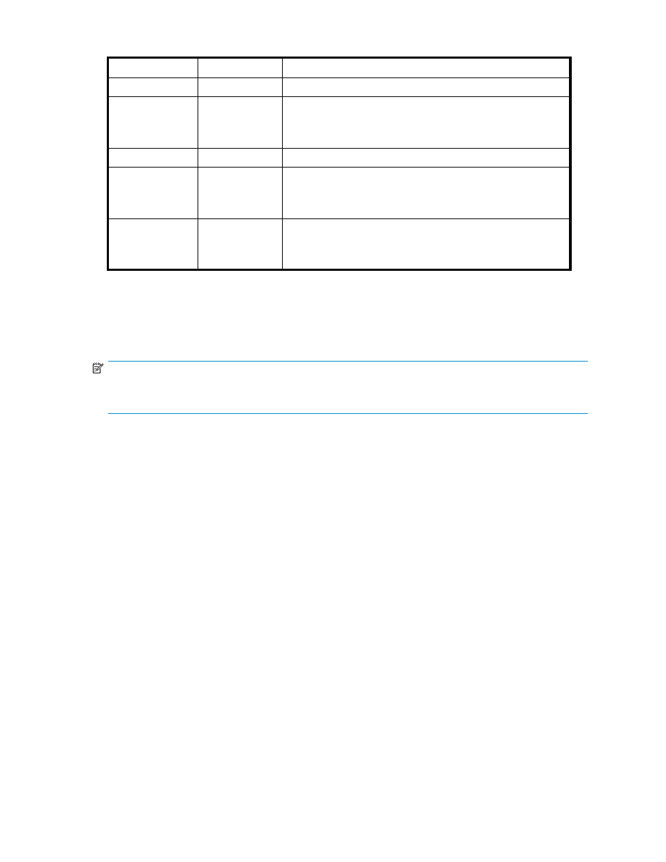
Table 28 Battery status indicators
Status indicator
Fault indicator
Description
On
Off
Normal operation
Flashing
Off
Battery is charging. This is the indication you will see when
installing a new battery. Charging also occurs during the
scheduled battery load test. The load test occurs infrequently and
takes several hours.
Off
On
Battery failure
Off
Flashing
Battery code is being updated. When a new battery is installed,
it may be necessary for the controllers to update the code on
the battery to the correct version. This typically takes less than a
minute.
Flashing
Flashing
Battery is undergoing a scheduled battery load test, during which
the battery is discharged and then recharged to ensure it is
working properly. During the discharge cycle, you will see this
display. The load test occurs infrequently and takes several hours.
HSV controller cabling
All data cables and power cables attach to the rear of the controller. Adjacent to each data connector is
a two-colored link status indicator.
identifies the status conditions presented by these indicators.
NOTE:
These indicators do not indicate whether there is communication on the link, only whether the link
can transmit and receive data.
The data connections are the interfaces to the disk drive enclosures or loop switches (depending on your
configuration), the other controller, and the fabric. Fiber optic cables link the controllers to the fabric,
and, if an expansion cabinet is part of the configuration, link the expansion cabinet drive enclosures to
the loop switches in the main cabinet. Copper cables are used between the controllers (mirror port) and
between the controllers and the drive enclosures or loop switches.
Racks
Each rack has four feet and four casters. Raising the adjustable feet places the rack weight on the casters,
so you can easily move the rack. Lowering the feet places the rack weight on the feet and prevents the
rack from moving. The removable front and rear doors, and the removable side panels provide easy
access to the rack interior.
Each configuration has an upper and lower controller enclosure (the controller pair), drive enclosures,
and an expansion bulkhead. Each controller pair and all the associated drive enclosures form a single
storage system.
Rack configurations
Each system configuration depends on the following factors:
•
The controller pair
•
The number of 3U Fibre Channel drive enclosures per rack
For more information about racks and configurations, including expansion and interconnection, refer to
the HP StorageWorks Enterprise Virtual Array hardware configuration guide.
4000/6000/8000 Enterprise Virtual Array user guide
79