Blowers, Drive enclosure emu, Controls and displays – HP 4000.6000.8000 Enterprise Virtual Arrays User Manual
Page 53: 18 emu location, 11 power supply/blower status indicators
Blowers
The power supply–mounted
cool the enclosure by circulating air through the enclosure. The
blowers, under the control of the EMU or the associated power supply, can operate at multiple speeds.
This ensures that when the enclosure temperature changes the blowers can automatically adjust the
air flow.
If a blower is operating too slowly or has stopped (a “blower failure”), internal circuitry automatically
operates the remaining blower at a higher speed. Simultaneously, the error condition is reported in
several ways, including the power supply indicator, the
, the enclosure fault indicators,
and the EMU alphanumeric display.
Should both blowers fail, the power supplies automatically shut down.
NOTE:
The blowers are field-replaceable units and can be replaced, individually, while the system is running.
The blowers are also interchangeable. The failure of a power supply +12.5 VDC circuit disables the
associated blower.
The status indicator on the blower (
) displays the status of both the power supply and the blower.
See
for definitions of the indicator displays.
Table 11 Power supply/blower status indicators
Blower status
LED
Description
On
Both the power supply and the blower are operational.
Flashing
The power supply or the blower locate function is active.
Off
The power supply or the blower is non–operational. When
there is a blower problem, the other blower runs at a higher
speed. Recommended corrective actions:
•
Check blower for proper operation. Replace if defective.
•
Check power supplies for proper operation. Replace if
defective.
Drive enclosure EMU
The EMU provides increased protection against catastrophic failures. The EMU detects conditions such
as failed power supplies, failed blowers, elevated temperatures, and external air sense faults and
communicates these conditions to the storage system controllers.
The EMU for Fibre Channel-Arbitrated Loop (FC–AL) drive enclosures is fully compliant with SCSI-3
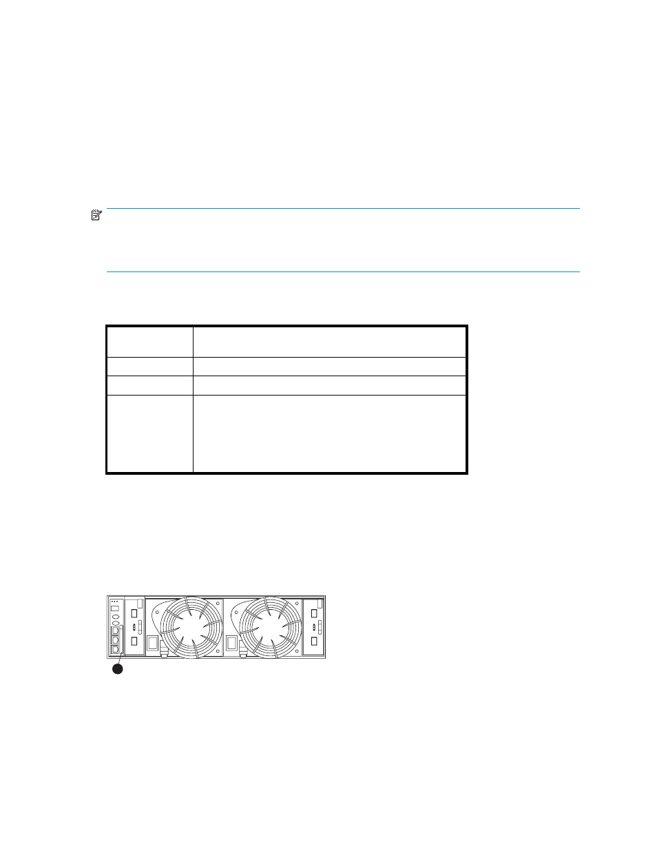
Enclosure Services (SES), and mounts in the left rear
of a drive enclosure (see 1,
).
CXO7971A
1
Figure 18 EMU location
1.
EMU
Controls and displays
illustrates the location and function of the EMU displays, controls, and connectors.
4000/6000/8000 Enterprise Virtual Array user guide
53