2 process values, 1 inputs and outputs, Inputs and outputs – NORD Drivesystems BU0550 User Manual
Page 87
4 Frequency inverter details
BU 0550 GB-0813
87
4.2 Process values
All analog and digital inputs and outputs or bus setpoints and actual values can be read and processed by
the PLC or can be set by the PLC (if they are output values. Access to the individual values is by means of
the process values listed below.
For all output values, the output (e.g. digital outputs or PLC setpoint) must be programmed so that the PLC
is the source of the event.
All process data is read in from the PLC by the FI at the start of each cycle and is only written to the
frequency inverter at the end of the program.
The following table lists all of the values which can be directly accessed by the PLC. All other process
values must be accessed via the function blocks MC_Readparameter or MC_WriteParameter.
4.2.1
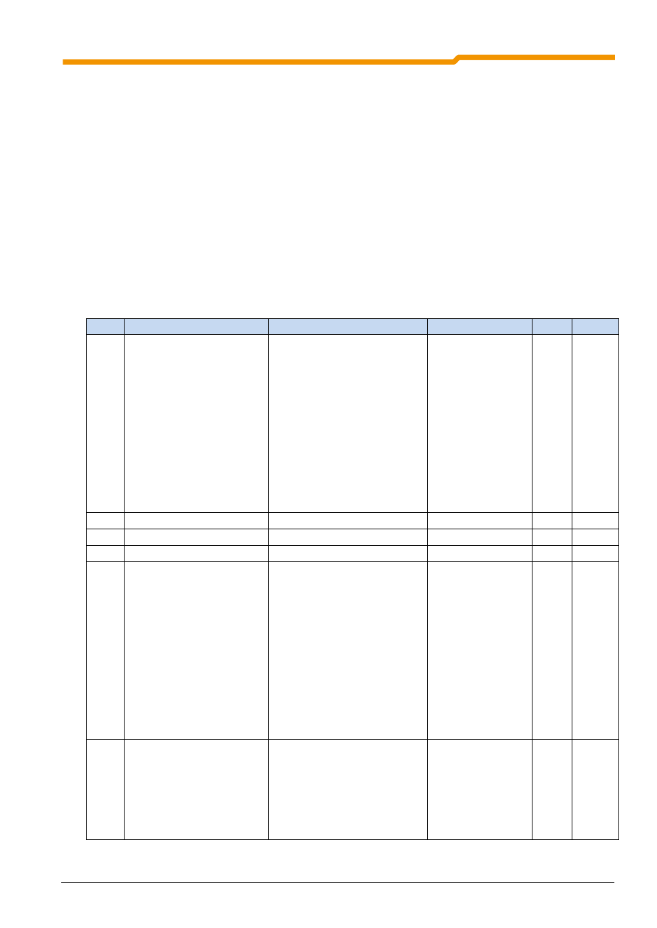
Inputs and outputs
Here, all process values which describe the I/O interface of the frequency inverter are listed.
Index Name
Function
Standardisation
Type
Access
0
_0_Set_digital_output
Set digital outputs
Bit 0: MFR1
Bit 1: MFR2
Bit 2: Dout1
Bit 3: Dout2
Bit 4: dig. funct. Aout
Bit 5: Dout3 (Din7)
Bit 6: Bus status word Bit 8
Bit 7: Status word Bit 9
Bit 8: BusIO Bit1
Bit 9: BusIO Bit2
Bit 10: BusIO Bit3
Bit 11: BusIO Bit4
Bit 12: BusIO Bit5
Bit 13: BusIO Bit6
Bit 14: BusIO Bit7
Bit 15: BusIO Bit8
INT
R/W
1
_1_Set_analog_output
Set analog output FI
10.0V = 100
BYTE
R/W
2
_2_Set_external_analog_out1 Set analog output 1 IOE
10.0V = 100
BYTE
R/W
3
_3_Set_external_analog_out2 Set analog output 2 IOE
10.0V = 100
BYTE
R/W
4
_4_State_digital_output
State of digital outputs
Bit 0: MFR1
Bit 1: MFR2
Bit 2: Dout1
Bit 3: Dout2
Bit 4: dig. funct. Aout
Bit 5: Dout3 (Din7)
Bit 6: Bus status word Bit 8
Bit 7: Status word Bit 9
Bit 8: BusIO Bit1
Bit 9: BusIO Bit2
Bit 10: BusIO Bit3
Bit 11: BusIO Bit4
Bit 12: BusIO Bit5
Bit 13: BusIO Bit6
Bit 14: BusIO Bit7
Bit 15: BusIO Bit8
INT
R
5
_5_Digital_input
State of digital inputs
Bit 0: DIN1
Bit 1: DIN2
Bit 2: DIN3
Bit 3: DIN4
Bit 4: DIN5
Bit 5: DIN6
Bit 6: DIN7
Bit 7: Digital function AIN1
Bit 8: Digital function AIN2
INT
R