NORD Drivesystems BU0550 User Manual
Page 61
3 AWL (Instruction List, IL)
BU 0550 GB-0813
61
3.5.3.2
FB_Gearing
The position and speed of the frequency inverter can be synchronised to that of a master inverter via the
function module FB_Gearing. The slave which used this function always follows the movements of the
master inverter.
The synchronisation is always absolute, i.e. the position of the slave and the master are always the same.
NOTE
If the slave is switched into gear mode when it is in a different position to the master, it then
moves to the master position at maximum frequency.
If a gear ratio is specified, this also results in a new position when switched on again.
The position value to which synchronisation is carried out, as well as the speed, must be communicated via
the Broadcast channel.
The function is activated via the ENABLE input; for this, the position control must be activated and the
output stage enabled. The output stage can be enabled e.g. with the function MC_Power. If ENABLE is set
to 0, the frequency inverter brakes to 0Hz and stops. The inverter is now once again in position control
mode.
If MC_Stop is activated, the frequency inverter exists from gear mode and the ABORT output is set to 1. In
case of errors in the FB, ERROR is set to 1 and the cause of the error is shown in ERRORID. ERROR,
ERRORID and ABORT can be reset by setting ENABLE to 0.
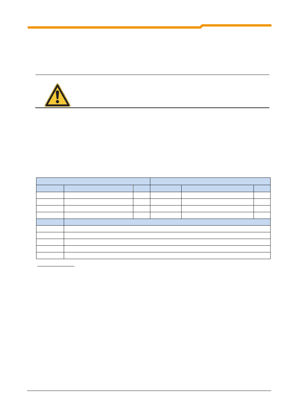
Table 87 FB_Gearing
Gear ratios or a change of direction of rotation can be set via the parameters P607[-05] or P608[-05] Further
details can be found in Manual BU0510 (Supplementary manual for POSICON position control).
3.5.3.3
FB_FlyingSaw
The Flying Saw function is an extension of the gear function. With the aid of this function it is possible to
synchronize a running drive unit to a precise position. In contrast to FB_Gearing, synchronisation is relative,
i.e. the slave axis moves synchronously to the position of the master which applied at the start of the "Flying
Saw" The synchronisation process is illustrated in the figure below.
VAR_INPUT
VAR_OUTPUT
Input
Explanation
Type
Output
Explanation
Type
ENABLE
Synchronous running active
BOOL
VALID
Gear unit function is active
BOOL
ABORT
Command aborted
BOOL
ERROR
Error in FB
BOOL
ERRORID
Error code
INT
ERRORID
Explanation
0
No error
1000h
FI is not enabled
1200h
Position control not activated
1201h
The PLC setpoint position High is not parameterised
1202h
The PLC setpoint position Low is not parameterised