West Control Solutions 8700+ User Manual
Page 52
1
/
4
-DIN,
1
/
8
-DIN &
1
/
16
- DIN Controllers & Indicators - Product Manual
59305, Issue 7
– March 2014
P6100, P8100 & P4100 Model Group
Page 47
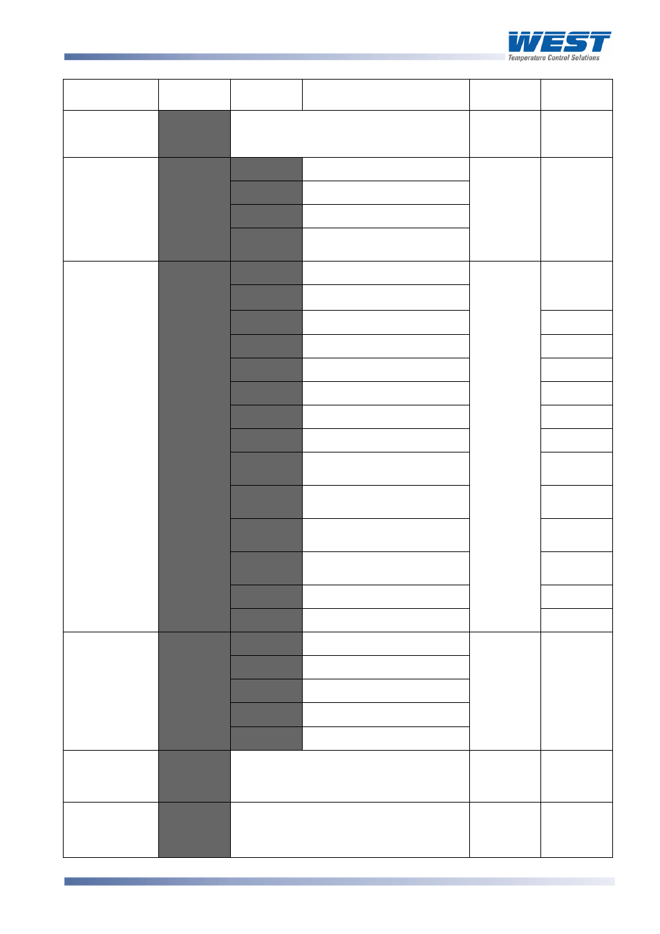
Parameter
Lower
Display
Upper
Display
Description
Default
Value
When
Visible
1 sec to 99 mins. 59secs
Only applies if primary proportional
band = 0
.
=
No alarms Inhibited
Always
Alarm 1 inhibited
Alarm 2 inhibited
Alarm 1 and alarm 2
inhibited
Output 1
Usage
Primary Power
is not
Secondary Power
Alarm 1, Direct Acting
Not linear
Alarm 1, Reverse Acting
Not linear
Alarm 2, Direct Acting
Not linear
Alarm 2, Reverse Acting
Not linear
Loop Alarm, Direct Acting
Not linear
Loop Alarm, Reverse Acting
Not linear
Logical Alarm 1 OR Alarm 2
Direct Acting
Not linear
Logical Alarm 1 OR Alarm 2
Reverse Acting
Not linear
Logical Alarm 1 AND Alarm
2, Direct Acting
Not linear
Logical Alarm 1 AND Alarm
2, Reverse Acting
Not linear
Retransmit SP Output
Linear only
Retransmit PV Output
Linear only
Linear Output
1 Range
0 to 5 V DC output 1
=
0 to 10 V DC output
2 to 10 V DC output
0 to 20 mA DC output
4 to 20 mA DC output
Retransmit
Output 1 Scale
maximum
to
Display value at which output will be
maximum
Range
max
=
or
Retransmit
Output 1 Scale
minimum
to
Display value at which output will be
minimum
Range min
=
or