Scale range lower limit, Type: general parameter, Secondary proportional band – West Control Solutions 8700+ User Manual
Page 158: Type: controller tuning parameter, Self-tune, Type: controller tuning definition, Self tune, Pre-tune, Secondary output proportional band, Secondary proportional band , self- tune
1
/
4
-DIN,
1
/
8
-DIN &
1
/
16
- DIN Controllers & Indicators - Product Manual
59305, Issue 7
– March 2014
Glossary
Page 153
Scale Range Lower Limit
Type: General Parameter
For linear inputs, this parameter can be used to display the process variable in engineering
units. It defines the displayed value when the process variable input is at its minimum value.
It is adjustable from -1999 to 9999 and can be set to a value more than (but not within 100
units of) the Scale Range Upper Limit, in which case the sense of the input is reversed.
For thermocouple and RTD inputs, this parameter is used to reduce the effective range of the
input. All span related functions, work from the trimmed span. The parameter can be
adjusted within the limits of the range selected by Configuration Mode parameter
. It is
adjustable to within 100 degrees of the Scale Range Upper Limit.
Display code =
, default value = 0 for linear inputs, or range minimum for temperature
inputs.
Also refer to Input Span, Process Variable and Scale Range Upper Limit.
Secondary Proportional Band
Type: Controller Tuning Parameter
The portion of the input span over which the Secondary Output power level is proportional to
the process variable value. It may be adjusted in the range 0.0% (ON/OFF) to 999.9%. The
Control action for the Secondary Output is always the opposite of the Primary output.
The Secondary Proportional Band is only applicable when Dual Control Type is used.
Display value =
, default value = 5.0%.
Also refer to Control Action, Control Type, On-Off Control, Input Span, Overlap/Deadband,
PID, Primary Proportional Band and Tuning.
Self-Tune
Type: Controller Tuning Definition
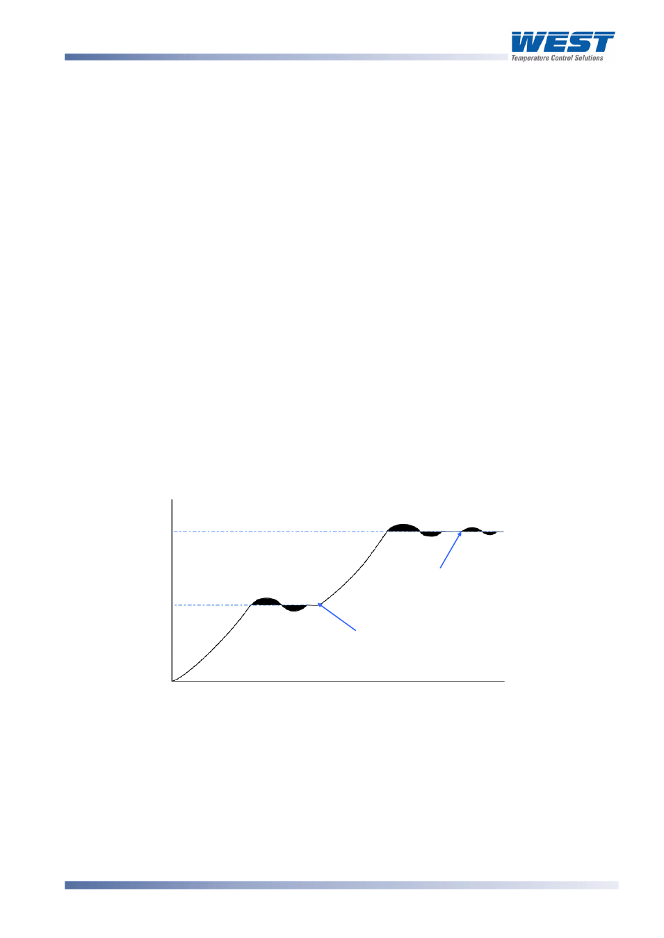
Self-Tune continuously optimises tuning while a controller is operating. It uses a pattern
recognition algorithm, which monitors the process error (deviation). The diagram shows a
typical application involving a process start up, setpoint change and load disturbance.
Figure 44.
Self-Tune Operation
The deviation signal is shown shaded and overshoots have been exaggerated for clarity.
The Self-Tune algorithm observes one complete deviation oscillation before calculating a set
of PID values. Successive deviation oscillation causes values to be recalculated so that the
controller rapidly converges on optimal control. When the controller is switched off, the final
PID terms remain stored in the controller's non-volatile memory, and are used as starting
values at the next switch on. The stored values may not always be valid, if for instance the
controller is brand new or the application has been changed. In these cases the user can
utilise Pre-Tune to establish new initial values.
Te
mperatu
re
Setpoint 1
Setpoint Change
Load Disturbance
Time
Setpoint 2