West Control Solutions 8700+ User Manual
Page 120
1
/
4
-DIN,
1
/
8
-DIN &
1
/
16
- DIN Controllers & Indicators - Product Manual
59305, Issue 7
– March 2014
P6010 & P8010 Model Group
Page 115
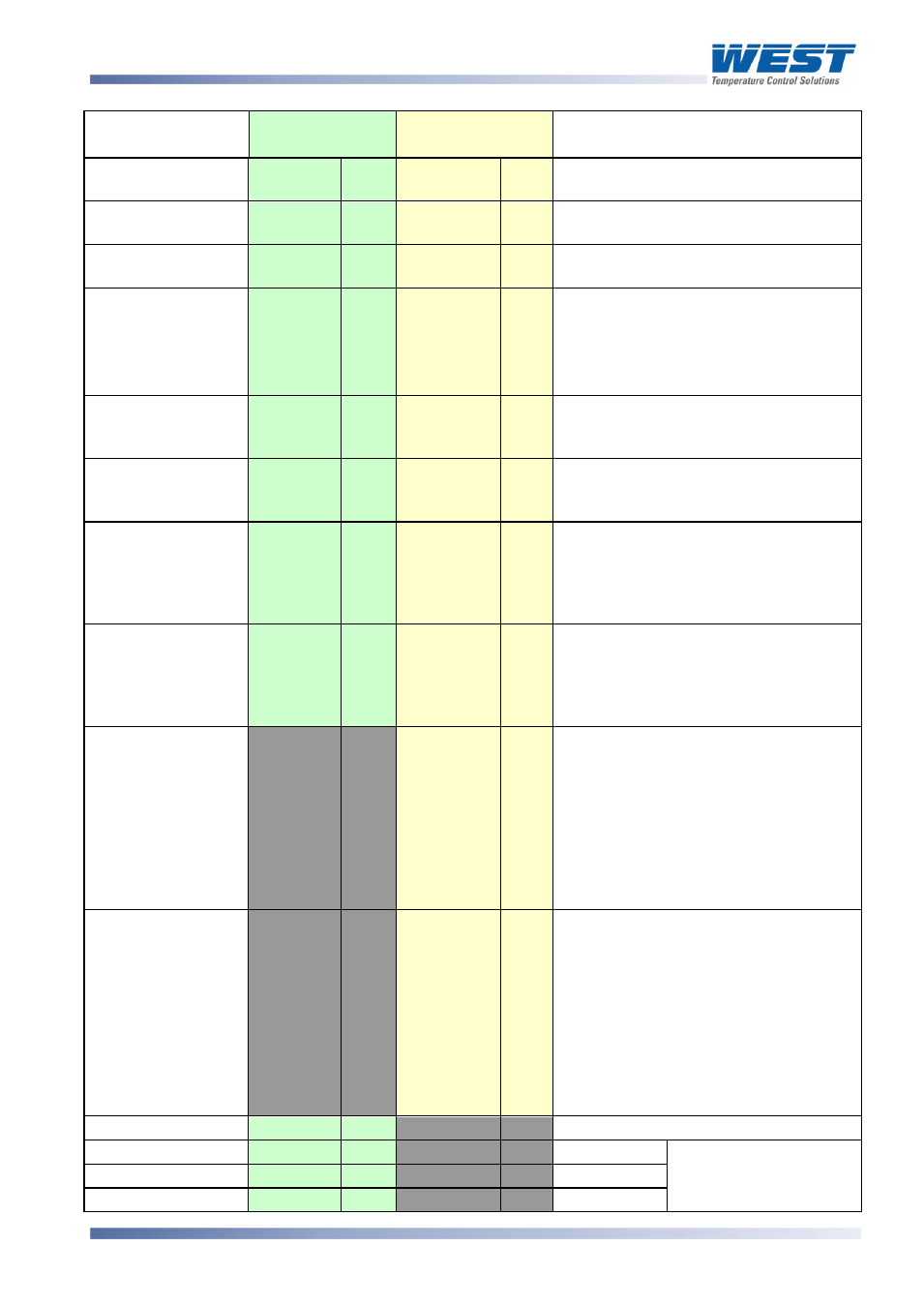
Parameter
Modbus
Parameter No.
ASCII Ident &
Message Types
Notes
11
R/W
F
Type 2, 3/4
R/W
0 to 100% of span
12
R/W
O
Type 2, 3/4
R/W
0 to 100% of span
13
R/W
m
Type 2, 3/4
R/W
0 to 100 seconds
Decimal Point
Position
14
R/W
Q
Type 2
Type 3/4
RO
R/W
0 = xxxx
1 = xxx.x
2 = xx.xx
3 = x.xxx
Read only if not Linear Input.
15
R/W
H
Type 2
Type 3/4
RO
R/W
Lower limit of scaled input range
16
R/W
G
Type 2
Type 3/4
RO
R/W
Upper limit of scaled input range
Re-transmit Output
Maximum
18
R/W
[
Type 2, 3/4
R/W
Maximum scale value for retransmit
output, 1999 to 9999. This parameter
applies to the first re-transmit output
fitted (see also Modbus parameters
2214, 2224 & 2234).
Re-transmit Output
Minimum
17
R/W
\
Type 2, 3/4
R/W
Minimum scale value for retransmit
output, 1999 to 9999. This parameter
applies to the first re-transmit output
fitted (see also Modbus parameters
2215, 2225 & 2235).
Scan Table
]
Type 2
R
Reads back main process values.
Response is: L{N}25aaaaabbbbb
cccccdddddeeeeeA* where:
aaaaa = Process Variable value
bbbbb = Stored Maximum PV value
ccccc = Stored Minimum PV value
ddddd = Stored Alarm 1 Elapsed Time
eeeee = Instrument Status (see
.
above)
Instrument
commands
Z
Type 3/4
WO
Only Type 3 / 4 ASCII messages are
allowed with this parameter. The
{DATA} field must be one of four 5-
digit numbers. The commands
corresponding to the {DATA} field
value are:
00150 = Unlatch Alarm 1 relay
00160 = Reset Stored Max PV
00170 = Reset Stored Min PV
00180 = Reset Alm1 Elapsed Time
Equipment ID
122
RO
The four digit model number 8010
Serial Number Low
123
RO
Digits aaaa
Unit serial number.
Format aaaa bbbb
cccc, (12 BCD digits).
Serial Number Mid
124
RO
Digits bbbb
Serial Number High
125
RO
Digits cccc