Operation – KROHNE IFC 100 Converter EN User Manual
Page 62
6
OPERATION
62
IFC 100
www.krohne.com
07/2010 - 4000041004 - MA IFC 100 R04 en
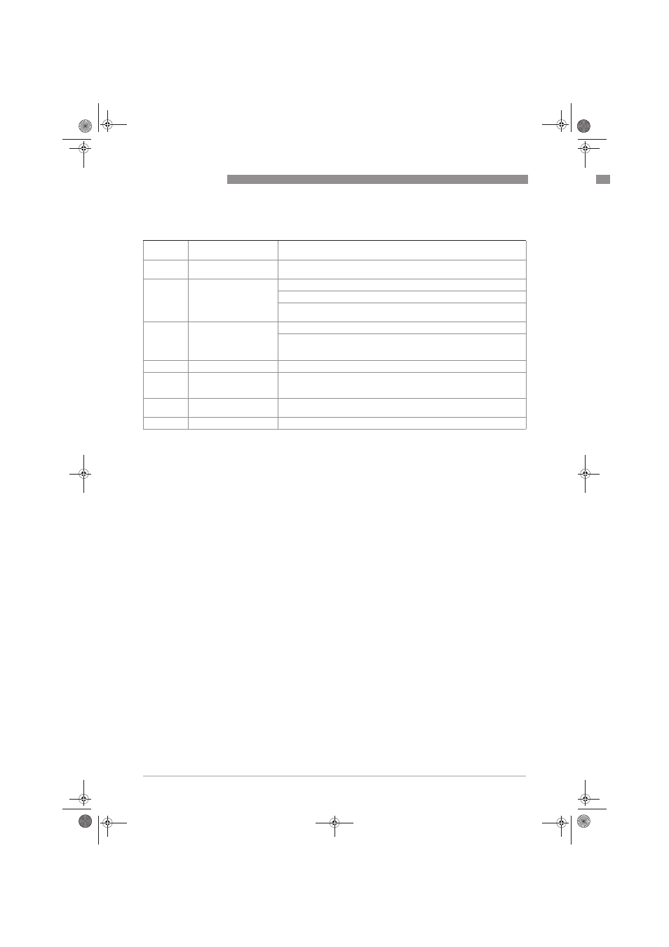
C2. limit switch X
C2.
limit switch X
X stands for one of the connection terminals C or D
stands for Fct. no. C2.4 (C) / C2.5 (D)
C2. .1
measurement
Select: volume flow / mass flow / diagnosis value / flow speed / coil
temperature / conductivity
C2. .2
threshold
Switching level, set threshold with hysteresis
xxx.x ±x.xxx (format and unit depend on the measurement, see above)
(1st value = threshold / 2nd value = hysteresis),
condition: 2nd value ≤ 1st value
C2. .3
polarity
Set polarity, please note flow direction in C1.2.2!
Select: both polarities (plus and minus values are displayed) / positive
polarity (display for negative values = 0) / negative polarity (display for
positive values = 0) / absolute value (use for the output)
C2. .4
time constant
Range: 000.1…100 s
C2. .5
invert signal
Select:
off (activated output generates a high current, switch closed) /
on (activated output generates a low current, switch open)
C2. .6
information
Serial number of the I/O circuit board, software version number and
production date of the circuit board
C2. .7
simulation
Sequence see B1. limit switch X
.book Page 62 Friday, July 9, 2010 12:29 PM