Operation, 2 menu structure – KROHNE IFC 100 Converter EN User Manual
Page 49
OPERATION
6
49
IFC 100
www.krohne.com
07/2010 - 4000041004 - MA IFC 100 R04 en
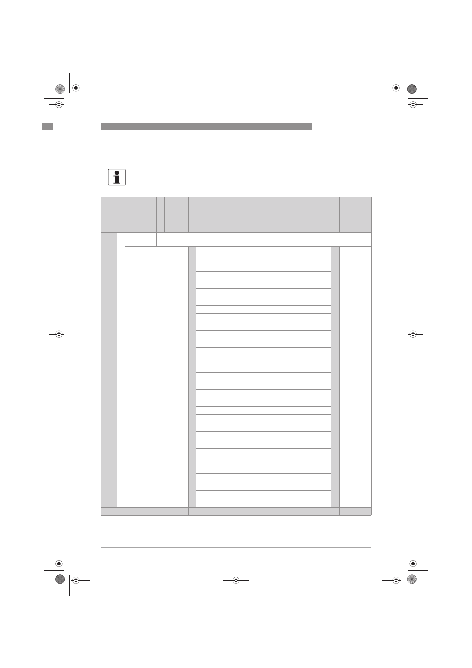
6.2 Menu structure
INFORMATION!
Note the key function within and between the columns.
Measuring mode
Select
menu
↓
↑
Select menu and/or sub-menu
↓ ↑
Select
function
and set
data
↓ ↑ >
^
Press
> 2.5 s
A quick setup
>
^
A1 language
>
^
A2 Tag
A3 reset
A3.1 reset errors
A3.2 counter 1
A3.3 counter 2
A4 analogue outputs
A4.1 measurement
A4.2 unit
A4.3 range
A4.4 low flow cutoff
A4.5 time constant
A5 digital outputs
A5.1 measurement
5.2 pulse value unit
A5.3 value p. pulse
A5.4 low flow cutoff
A7 process input
A7.1 device serial no.
A7.2 zero calibration
A7.3 size
A7.5 GKL
A7.6 coil resistance Rsp
A7.7 calib. coil temp.
A7.8 target conduct.
A7.9 EF electr. factor
A7.10 field frequency
A7.11 flow direction
^
B test
>
^
B1 simulation
>
^
B2 actual values
B3 information
↓ ↑
↓ ↑
↓ ↑
↓ ↑ >
.book Page 49 Friday, July 9, 2010 12:29 PM
- BATCHFLUX 5500 C Quickstart EN (20 pages)
- IFC 050 Converter Quickstart EN (28 pages)
- IFC 100 Converter Quickstart EN (32 pages)
- IFC 300 Converter Quickstart EN (68 pages)
- OPTIFLUX 1000 Quickstart EN (20 pages)
- OPTIFLUX 2000 Quickstart EN (24 pages)
- OPTIFLUX 4000 Quickstart EN (24 pages)
- OPTIFLUX 4040C Quickstart EN (16 pages)
- OPTIFLUX 5000 Flange Quickstart EN (20 pages)
- OPTIFLUX 5000 Sandwich Quickstart EN (20 pages)
- OPTIFLUX 6000 Quickstart EN (28 pages)
- OPTIFLUX 7300 Quickstart EN (24 pages)
- OPTIPROBE Quickstart EN (16 pages)
- TIDALFLUX 2300 F EN (44 pages)
- TIDALFLUX 2300 F Quickstart EN (24 pages)
- WATERFLUX 3000 EN (40 pages)
- WATERFLUX 3000 Quickstart EN (24 pages)
- WATERFLUX 3070 EN (80 pages)
- WATERFLUX 3070 Quickstart EN (32 pages)
- USB ADAPTER PLUS EMF EN (16 pages)
- IFC 050 Converter Modbus EN (20 pages)
- IFC 100 Converter FOUNDATION FIELDBUS EN (64 pages)
- IFC 100 Converter Modbus EN (20 pages)
- IFC 300 Converter FOUNDATION FIELDBUS EN (60 pages)
- IFC 300 Converter HART 0102 EN (20 pages)
- IFC 300 Converter HART 0201 EN (23 pages)
- IFC 300 Converter Modbus EN (24 pages)
- IFC 300 Converter PROFIBUS PA DP EN (40 pages)
- OPTIFLUX 2000-4000 IECEx EN (16 pages)
- OPTIFLUX 2000-4000-5000-6000-7300-IFC 300 Ex EN (40 pages)
- OPTIFLUX 2000-4000-5000-6000 -IFC 100 Ex EN (24 pages)
- OPTIFLUX 4040 C Ex EN (20 pages)
- OPTIFLUX x300 Ex Zone2 EN (1 page)
- H250 M9 ES EN (36 pages)
- VA 40-VA 45 EN (36 pages)
- H250 M10 ATEX II2G Ex d EN (16 pages)
- H250 M10 ATEX II3D Ex t EN (16 pages)
- H250 M40 ATEX II2D Ex t-II2G Ex d EN (20 pages)
- H250 M40 ATEX II2G Ex i EN (20 pages)
- H250 M40 ATEX II3G Ex nA EN (20 pages)
- H250 M40 Ex II2G Reed EN (2 pages)
- H250 M9 ATEX II2G Ex i EN (16 pages)
- H250 M9S ATEX II3D Ex t-II3G Ex nA EN (20 pages)
- M8E Converter HART 0101 EN (13 pages)
- DK 32-DK 34 ATEX II2G Ex i EN (16 pages)