Electrical connections – KROHNE IFC 100 Converter EN User Manual
Page 42
4
ELECTRICAL CONNECTIONS
42
IFC 100
www.krohne.com
07/2010 - 4000041004 - MA IFC 100 R04 en
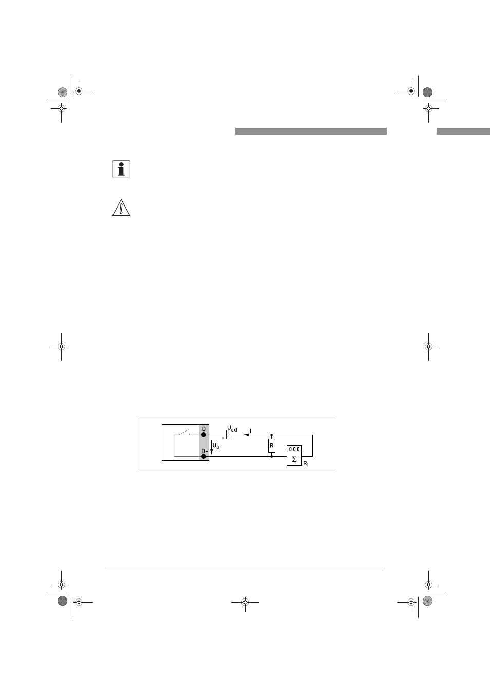
Pulse/frequency output passive
• U
ext
≤ 32 VDC
• f
max
in operating menu set to 100 Hz < f
max
≤ 10 kHz:
I ≤ 100 mA at ≤ 10 kHz (overcontrol up to f
max
≤ 12 kHz)
open:
I ≤ 0.1 mA at U
ext
= 5 V
I ≤ 0.5 mA at U
ext
= 24 V
I ≤ 0.7 mA at U
ext
= 32 V
closed:
U
0, max
= 0.8 V at I ≤ 1 mA
U
0, max
= 1.5 V at I ≤ 10 mA
U
0, max
= 3.5 V at I ≤ 100 mA
• If the following maximum load resistance R
L, max
is exceeded, the load resistance R
L
must be
reduced accordingly by parallel connection of R:
f ≤ 1 kHz: R
L, max
= 10 kΩ
f ≤ 10 kHz: R
L, max
= 2 kΩ
• The minimum load resistance R
L, min
is calculated as follows:
R
L, min
= (U
ext
- U
0
) / I
max
• Can also be set as status output; for the electrical connection refer to status output
connection diagram.
• The output is closed when the device is de-energized.
INFORMATION!
•
For frequencies above 100 Hz, shielded cables are to be used in order to reduce effects from
electrical interferences (EMC).
•
Shielding takes place at the electrical connection (S) of the output terminal block.
CAUTION!
Observe connection polarity.
Figure 4-18: Pulse/frequency output passive P
p
.book Page 42 Friday, July 9, 2010 12:29 PM