Table 3-10. ieee 488 (gpib) bus data mode messages, 1 gpib port setup, 1 changing the gpib address – KEPCO BOP-GL 1KW Operator Manual Firmware Ver.3.05 and higher User Manual
Page 91: 2 configure device clear (dcl) control, Gpib port setup -29, Changing the gpib address -29, Configure device clear (dcl) control -29, 10 ieee 488 (gpib) bus data mode messages -29, S 3.6.3.1
BOP-1K-GL 022814
3-29
3.6.3.1
GPIB PORT SETUP
The following paragraphs describe the how to configure the GPIB port.
3.6.3.1.1 CHANGING THE GPIB ADDRESS
The default address is 6. To change the GPIB address use the SYST:COMM:GPIB:ADDR com-
mand (PAR B.122). To configure a particular GPIB address to implemented upon power-up,
refer to PAR. 3.3.2.2).
3.6.3.1.2 CONFIGURE DEVICE CLEAR (DCL) CONTROL
The device clear (DCL) and selected device clear can be set to operate in two modes. In the
MATE mode (DCL1), when the device clear is received, the output of the power supply is set to
zero volts. In the SCPI mode (DCL0) sending DCL or selected DCL has no effect on output volt-
age and current as required by IEEE specification 488.2. The factory default value is SCPI
mode (DCL0) (see PAR. B.144).
IFC
Interface Clear
Received
MLA
My Listen Address
Received
MTA
My Talk Address
Received
OTA
Other Talk Address
Received
RFD
Ready for Data
Received or Sent
SDC
Selected Device Clear
Received
SPD
Serial Poll Disable
Received
SPE
Serial Poll Enable
Received
SRQ
Service Request
Sent
UNL
Unlisten
Received
UNT
Untalk
Received
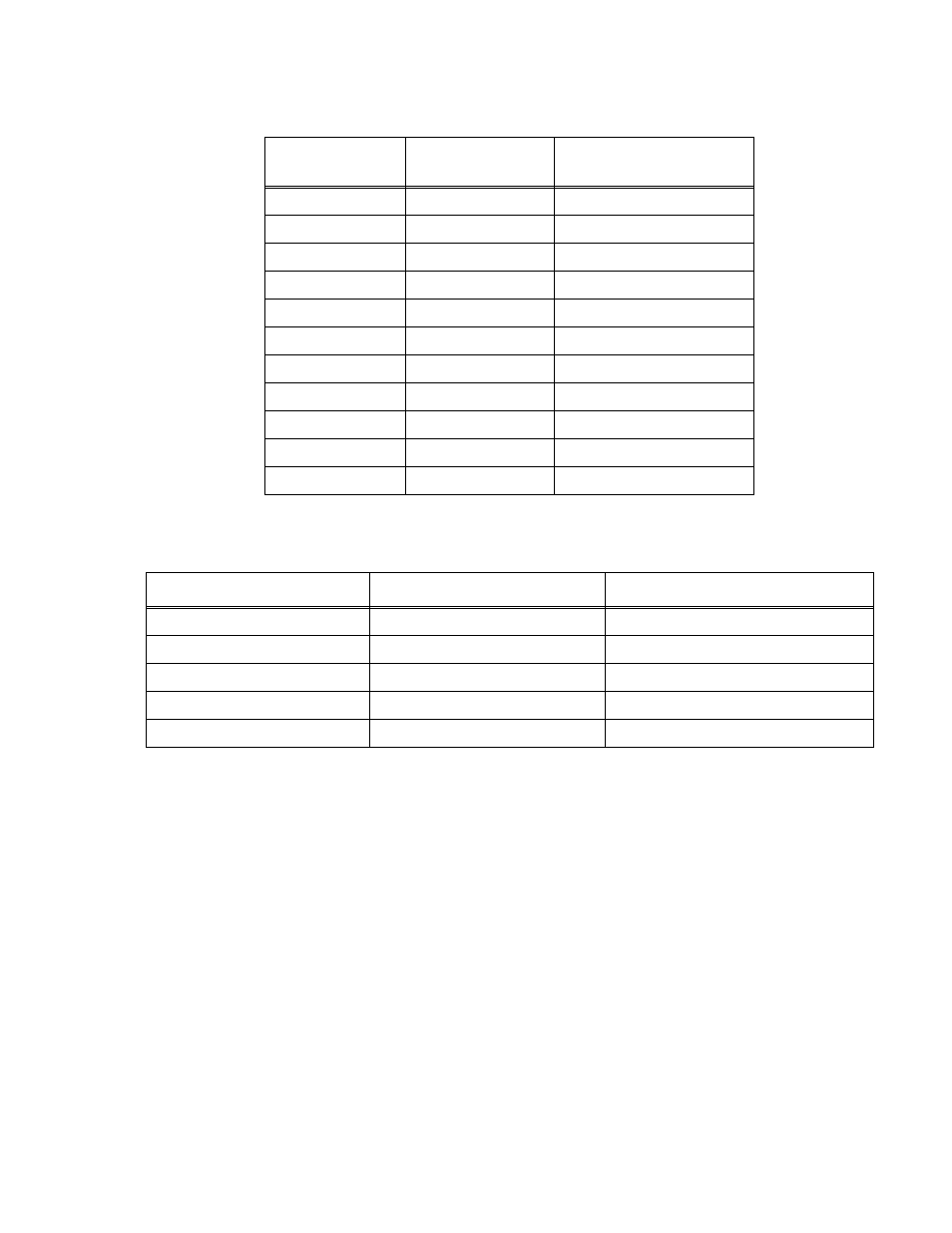
TABLE 3-10. IEEE 488 (GPIB) BUS DATA MODE MESSAGES
MNEMONIC
MESSAGE DESCRIPTION
COMMENTS
DAB
Data Byte
Received or Sent
END
End
Received or Sent
EOS
End of String
Received or Sent
RQS
Request Service
Sent
STB
Status Byte
Sent
TABLE 3-9. IEEE 488 (GPIB) BUS COMMAND MODE MESSAGES (CONTINUED)
MNEMONIC
MESSAGE
DESCRIPTION
COMMENTS