Section 1 - introduction, 1 scope of manual, 2 general description – KEPCO BOP-GL 1KW Operator Manual Firmware Ver.3.05 and higher User Manual
Page 19: 3 specifications, Table 1-1. bop-gl 1000 watt model parameters, Scope of manual -1, General description -1, Specifications -1, Bop-gl 1000 watt model parameters -1
BOP-1K-GL 022814
1-1
SECTION 1 - INTRODUCTION
1.1
SCOPE OF MANUAL
This manual contains instructions for the installation, operation and servicing of the BOP-GL
series of 1000 Watt rack-mounted, 4-quadrant bipolar, programmable, voltage and current stabi-
lized d-c power supplies manufactured by Kepco, Inc., Flushing, New York, U.S.A.
1.2
GENERAL DESCRIPTION
The BOP-GL Series (Figure 1-1), are true 4-quadrant programmable voltage and current power
supplies, meaning they are capable of both sourcing and sinking power. The BOP-GL models
hereafter referred to as BOP, have been optimized for exceptionally low current ripple and noise
and improved stability (drift and temperature), making them ideal for driving inductive loads such
as large magnets or motors. These bipolar power supplies pass smoothly through zero without
switching to provide true ± voltage and ± current. These BOP power supplies use switch mode
technology for low dissipation. A bi-directional, isolating, a-c input power factor correcting (PFC)
circuit recuperates energy sunk from an active load and sends it back into the line to maintain
low dissipation.
These BOP power supplies can be controlled remotely by an analog ±10V input for the main
channel (voltage or current), and by a +1 to +10V input for the limit channels. They can also be
controlled through one of the standard digital interfaces (GPIB or RS 232) to set voltage and
current and the four protection limits (+voltage, –voltage, +current and –current.) Output voltage
and current can be remotely monitored via the analog monitor signals present at the rear panel
Analog I/O Port connector, or by using SCPI commands via either the RS 232 or GPIB ports.
1.3
SPECIFICATIONS
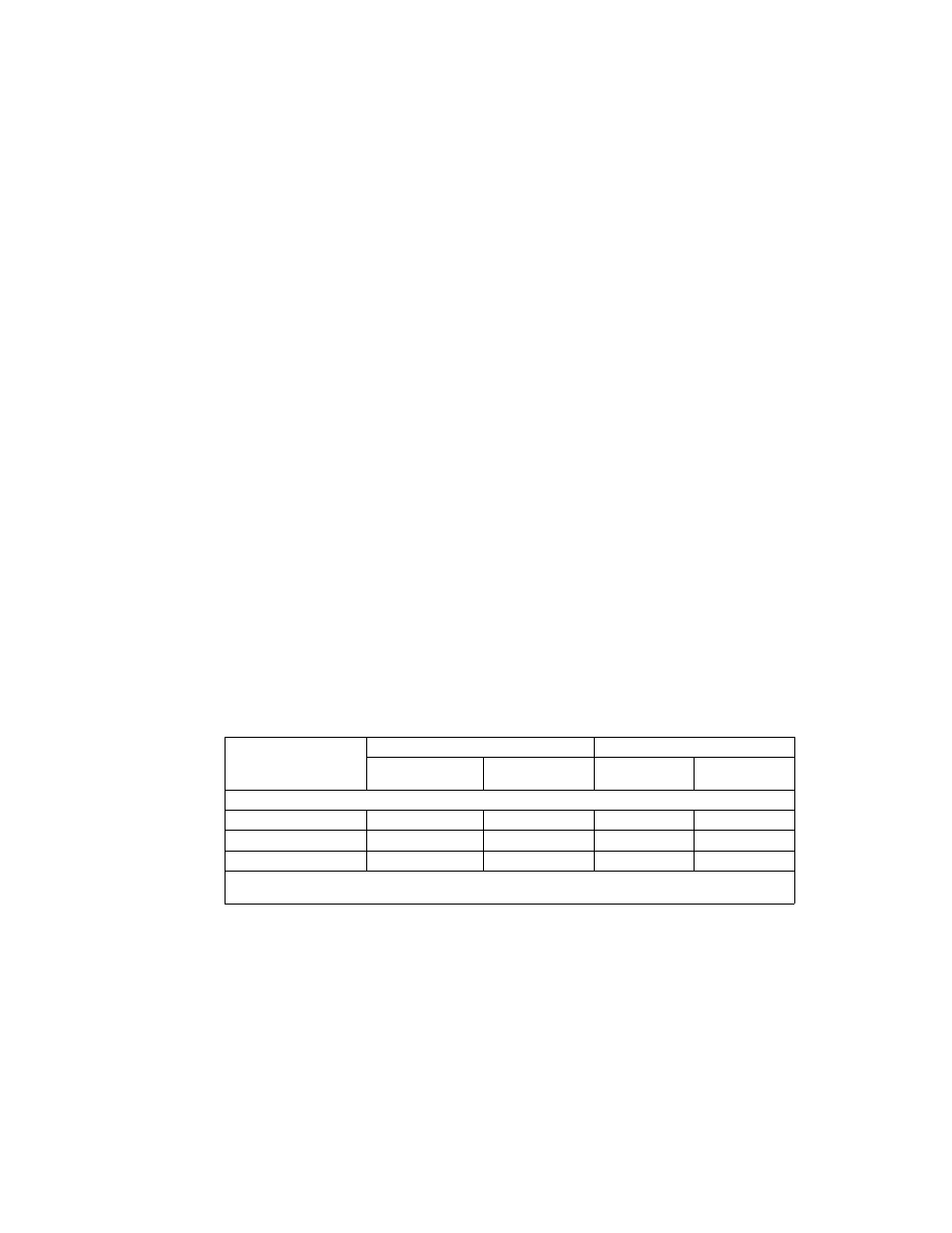
Table 1-1 below indicates parameters that vary for different 1000 Watt BOP-GL models; Table 1-
2 lists general specifications that apply to all 1000 Watt BOP-GL models.
TABLE 1-1. BOP-GL 1000 WATT MODEL PARAMETERS
Model
d-c Output Range
Closed Loop Gain
E
O Max
I
O Max
Voltage
Channel
Current
Channel
1000 WATT MODELS
BOP 10-100GL
±10V d-c
±100A d-c
1.0
10.0
BOP 20-50GL
±20V d-c
±50A d-c
2.0
5.0
BOP 50-20GL
±50V d-c
±20A d-c
5.0
2.0
NOTE: When connecting active loads, the steady-state voltage of the active load must not exceed the maximum
voltage rating of the BOP. Otherwise the overvoltage protection will shut down the power supply.