Figure 2-2. bop-gl top cover accessible components, Table 2-2. power-up setup switches, Bop-gl top cover accessible components -3 – KEPCO BOP-GL 1KW Operator Manual Firmware Ver.3.05 and higher User Manual
Page 39: Power-up setup switches -3, Re 2-2 an
BOP-1K-GL 022814
2-3
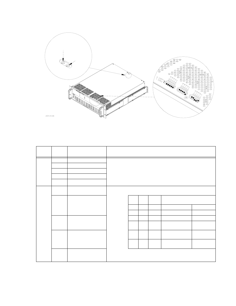
FIGURE 2-2. BOP-GL TOP COVER ACCESSIBLE COMPONENTS
TABLE 2-2. POWER-UP SETUP SWITCHES
SWITCH
(FIGURE
2-2)
SECTION
FUNCTION
DESCRIPTION
S1
S1-1
Bit 1 (LSB)
1. Enable the GPIB address from 0 [00000] to 30 [11110]) while reading power-
up switches S2 and S3 during a normal power-up (see PAR. 3.3.2.2 for
details).
2. Address 31 (11111) initiates a special power-up reset which resets the limits
to factory defaults (see PAR. B.143), allows selection of Load type, allows
selection of Remote on-off logic at Trigger port pin 2 and selection of RS 232
baud rate. (see PAR. 3.3.2.1 for details)
S1-2
Bit 2
S1-3
Bit 3
S1-4
Bit 4
S1-5
Bit 5 (MSB)
S2
S2-1
Master or Standalone (1)
Slave (0)
Establish whether the unit is standalone or designated as master or slave in a
multiunit series or parallel configuration
S2-2
Series (1)
Parallel (0)
S2-5 S2-4
S2-3
(LSB)
Configure unit as
S2-1 = 1
S2-1 =0
0
0
0
Standalone
N/A
S2-3
Bit 1 (LSB)
(see Table at right)
0
0
1
Master with 1 slave
Slave #1
0
1
0
Master with 2 slaves
(1)
Slave #2
(1)
S2-4
Bit 2
(see Table at right)
0
1
1
Master with 3 slaves
(1)
Slave #3
(1)
1
0
0
Master with 4 slaves
(1)
Slave #4
(1)
S2-5
Bit 3
(see Table at right)
NOTE: the unit will beep if the above switches are set to 110 or
111 (invalid setting). The unit will not beep if the switches are
set to 010, 011, 100, or 101 (2, 3, 4, or 5 slaves).
(1) Consult factory to implement configurations of more than one slave.
POWER-UP SETUP
SWITCHES
VOLTAGE MONITOR
ZERO ADJ
A2A5R85
CALIBRATION
ADJUSTMENTS
VOLTAGE MONITOR
FULL SCALE ADJ
(A2A5R89)
S3
S1
S2