2 multiple unit source power, 3 multiple unit protection, Multiple unit source power -24 – KEPCO BOP-GL 1KW Operator Manual Firmware Ver.3.05 and higher User Manual
Page 60: Multiple unit protection -24
2-24
BOP-1K-GL 022814
2.8.2
MULTIPLE UNIT SOURCE POWER
When multiple units are connected in series or parallel, the individual power supplies of the sys-
tem may be connected to different phases of a 3-phase a-c power source.
2.8.3
MULTIPLE UNIT PROTECTION
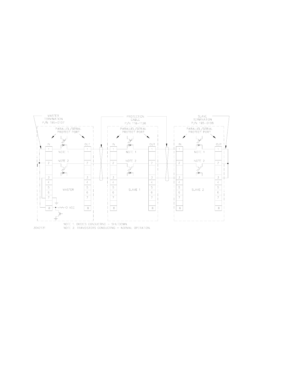
For multiple unit configurations it is necessary to configure the protection so that a fault will shut
down all the interconnected power supplies. Figure 2-11 is a simplified diagram showing typical
protection interconnections for master/slave configurations. These interconnections are done
using the special cables and terminations supplied in the applicable Interconnection Kit avail-
able as an accessory (see Table 1-5).
FIGURE 2-11. TYPICAL MASTER/SLAVE PROTECTION INTERCONNECTIONS
Upon startup, PAR/SER PROT IN PORT pin 8 of the master goes low, and stays low until all
slaves are powered up. Normal power up of a unit causes the transistor connecting PAR/SER
PROT IN PORT pin 2 and PAR/SER PROT OUT PORT pin 2 to conduct. The transistors of all
units are connected in series, effectively shorting out all the shutdown diodes (the shutdown
diodes of all units are also connected in series) connecting PAR/SER PROT IN PORT pin 1 and
PAR/SER PROT OUT PORT pin 1. After all the units are powered up and operating normally,
the low at PAR/SER PROT IN PORT pin 8 changes to high, but the conducting transistors keep
the voltage at pin 8 low and the diodes are cut off. If a fault occurs, the transistor between PAR/
SER PROT IN PORT pin 2 and PAR/SER PROT OUT PORT pin 2 of the defective unit is cut off,
allowing current to flow through the shutdown diodes. This develops internal shutdown signals
that shut down all units.