2 test equipment requirements, Table 4-2. suggested sense resistors, Test equipment requirements -3 – KEPCO BOP-GL 1KW Operator Manual Firmware Ver.3.05 and higher User Manual
Page 113: Suggested sense resistors -3, Voltage calibration measurements and tolerances -3, Ar. 4.3)
BOP-1K-GL 022814
4-3
4.2
TEST EQUIPMENT REQUIREMENTS
Table 4-2 lists sense resistors recommended for measuring current and includes Kepco and
Manufacturer’s part numbers. The value of the sense resistor chosen should be known with
0.001% accuracy. If other than a recommended sense resistor is to be used, it must be rated for
at least 100W power dissipation (actual power dissipation will be approximately 10W). The ther-
mal coefficient of the sense resistor chosen should be 10 ppm/°C or better. Other high-precision
and high-stability current measurement devices (such as a zero flux current transducer) can
also be used for output current calibration and evaluation.
The digital voltmeter (DVM) used to measure output voltage and the voltage across the current
sensing resistor should have at least six digits, multiple ranges, the smallest resolution must be
at least one microvolt and the accuracy must be at least 0.0001%.
To calibrate the external programming capabilities of the BOP a DC reference voltage with the
following minimum specifications is required.
•
Value: 0.0V ±0.1mV and 10.0V ±0.1mV (either positive and negative or floating)
•
Stability: better than 10
-5
•
Internal Impedance: better than 0.1 Ohms
•
Output Current: >0.5mA when sourcing, >0.15mA when sinking
4.3
CALIBRATION USING REMOTE SCPI COMMANDS VIA GPIB OR RS 232 INTERFACE
The primary means of adjustment are the
CAL:DATA
commands. Basically these commands
are fine and coarse adjustments, however there are slight differences in how they work for dif-
ferent types of calibrations.
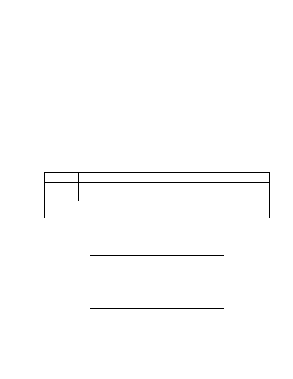
TABLE 4-2. SUGGESTED SENSE RESISTORS
MODEL
VALUE
KEPCO PART NO.
MANUFACTURER
MANUFACTURER PART NO.
BOP 10-100GL
BOP 20-50GL
0.001 OHM
115-3033
ISOTEK
RUG-Z-R001-0.1 TK10
BOP 50-20GL
0.01 OHM
115-2997
ISOTEK
RUG-Z-R010-0.1 TK10
NOTE: ALL SENSE RESISTORS MUST BE MOUNTED ON A HEATSINK WITH A MINIMUM SURFACE AREA OF 36 SQUARE
INCHES TO MAINTAIN THERMAL STABILITY DURING CALIBRATION; FORCED CCOOLING IS RECOMMENDED.
KEPCO HEATSINK P/N 136-0451 WILL PROVIDE ADQUATE COOLING FOR THE SENSE RESISTOR.
TABLE 4-3. VOLTAGE CALIBRATION MEASUREMENTS AND TOLERANCES
MODEL
VOLTAGE
ZERO
±FULL SCALE
VOLTAGE
±FULL SCALE
VPR LIMIT
BOP 10-100GL
0V
±0.0001V
10V (MAX)
-10V (MIN)
±0.001V
10V (MAX)
-10V (MIN)
±0.003V
BOP 20-50GL
0V
±0.0002V
20V (MAX)
-20V (MIN)
±0.002V
20V (MAX)
-20V (MIN)
±0.006V
BOP 50-20GL
0V
±0.005V
50V (MAX)
-50V (MIN)
±0.005V
50V (MAX)
-50V (MIN)
±0.015V