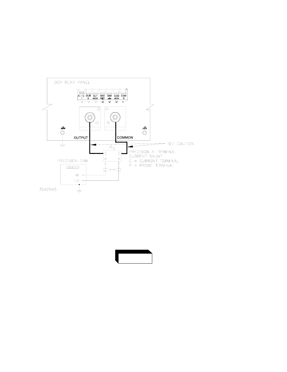
Figure 4-2. calibration setup in current mode, Calibration setup in current mode -8, Refer to figure 4-2 to connect – KEPCO BOP-GL 1KW Operator Manual Firmware Ver.3.05 and higher User Manual
Page 118
4-8
BOP-1K-GL 022814
resistor ((LO terminal of DVM to common P terminal). Table 4-4 provides recommended
sense resistor values for various BOP current outputs, as well as the formula for calculating
expected measured values and tolerances for any sense resistor other than those recom-
mended. Table 4-2 lists Kepco and Manufacturer part numbers for those sense resistors rec-
ommended.
FIGURE 4-2. CALIBRATION SETUP IN CURRENT MODE
22.Set the BOP to zero volts across the sense resistor (corresponding to zero current) by send-
ing
CAL:CURR ZERO
. Send
CAL:DATA
commands as needed (see PAR. 4.3a) until the
reading is as close to zero as possible within the limits specified in Table 4-4 for CURRENT
ZERO.
The sense resistor will be dissipating full rated current of the BOP. If
it is hot to the touch, the sense resistor value, power rating and/or
cooling are incorrect; refer to PAR. 4.3 and Table 4-2.
23.Set the BOP to maximum positive output current by sending
CAL:CURR MAX
. Measure the
current by reading the voltage across the sense resistor. To adjust, send
CAL:DATA
com-
mands as needed (see PAR. 4.3b) to adjust the BOP output until the DVM reads as close as
possible above the nominal full scale value within tolerance specified in Table 4-4 for +FULL
SCALE CURRENT.
CAUTION
WIRES BETWEEN BOP OUTPUT AND
SENSE RESISTOR MUST BE RATED TO
CARRY THE RATED OUTPUT
CURRENT OF THE POWER SUPPLY.
AWG#6 IS RECOMMENDED.
WARNING