Figure 3-1. bop-gl series front panel, Table 3-1. front panel controls and indicators, 2 turning the power supply on – KEPCO BOP-GL 1KW Operator Manual Firmware Ver.3.05 and higher User Manual
Page 65: Turning the power supply on -3, Bop-gl series front panel -3, Front panel controls and indicators -3, 1 an, D 3-1 fo, 1 ex, E 3-1 an
BOP-1K-GL 022814
3-3
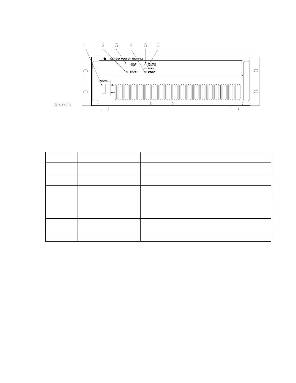
FIGURE 3-1. BOP-GL SERIES FRONT PANEL
3.3.2
TURNING THE POWER SUPPLY ON
The status of the unit upon power-up depends on the configuration of the three power-up
switches (see Figure 2-2 and Table 2-2). Each power-up switch has five segments. For conve-
nience the switch settings are often given for all segments as e.g., 00110 indicates segments 5,
4 and 1 are off (0) and segments 2 and 3 are on (1). In other instances a particular segment
(e.g., S3-5) is specified.
The reset power-up (PAR. 3.3.2.1) allows the power-up switches to establish 1) load type, 2)
Remote On/off logic at Trigger port pin 2 and 3) baud rate. The reset power-up also resets all
limits to the factory default condition (see PAR. B.143). The normal power-up (PAR. 3.3.2.2)
establishes the operating mode of the unit, whether control will be analog or digital, whether the
unit is standalone or part of a multi-unit configuration, and selects the GPIB address to be used
(see Table 2-2 for details).
TABLE 3-1. FRONT PANEL CONTROLS AND INDICATORS
NUMBER
(FIGURE 3-1)
CONTROL/INDICATOR
FUNCTION
1
POWER ON/OFF
circuit breaker A7CB1
Applies source power to unit.
2
OUTPUT ON LED
Provides Output Status. Lights green for OUTPUT ON, not lit for output
off.
3
Unit Status
POWER/FAULT/LIMIT LED
Lights green for POWER good, lights red for FAULT, lights orange for
LIMIT.
4
Configuration Type
MASTER/SLAVE LED
Lights green for MASTER or Standalone, lights yellow for SLAVE. For
multiunit configuration, this flashes (either green or yellow) to indicate unit
is a master, and is looking for slaves. If flashing continues, refer to PAR.
3.8 for troubleshooting.
5
Mode of Operation
VOLTAGE/CURRENT LED
Flashes during power-up while configuration is established. Lights green
for VOLTAGE mode, lights yellow for CURRENT mode. If flashing contin-
ues, refer to PAR. 3.8 for troubleshooting.
6
DIG. CTRL LED
Lights green for digital control, not lit for Analog Control.