Caution, A-c wiring (e.g., defeating of ground connection), 11 analog i/o port input/output pin assignments -8 – KEPCO BOP-GL 1KW Operator Manual Firmware Ver.3.05 and higher User Manual
Page 44: Able 2-11), Able 2-11, E 2-11.)
2-8
BOP-1K-GL 022814
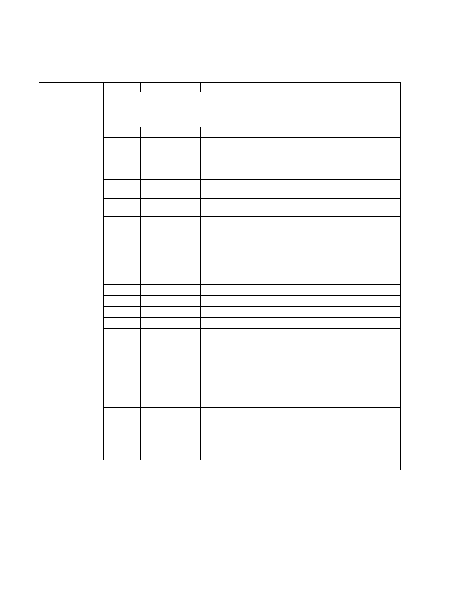
TABLE 2-11. ANALOG I/O PORT INPUT/OUTPUT PIN ASSIGNMENTS
CONNECTOR
PIN
SIGNAL NAME
FUNCTION
ANALOG I/O
PORT
A2A5J6
CAUTION: it is recommended that source power of external equipment connected to the Analog
Port be applied through an isolating transformer to avoid ground loops or possible
damage to the BOP due to incorrect equipment a-c wiring (e.g., defeating of ground
connection).
1
NC
2
VM-/CM
External input signal, TTL logic referenced to pin 9, controls the mode
of operation when using external reference (goes to the digital board
that changes VM-/CM signal). Logic 0 (or pin grounded) = current
mode, logic 1 (or pin not connected, the default) = voltage mode (see
PAR. 3.4.1).
3
IOUT_DMM
Output analog signal referenced to pin 4 for monitoring output current,
0V to ± 10V corresponds to zero to ± full scale current.
4
SGND
Signal Ground used for IOUT_DMM (pin 3) and VOUT_DMM (pin 15)
return.
5
– I_LIM_EXT
Analog input signal referenced to pin 12, 0V to +10V sets the negative
current limit between zero and –I
Omax
, +10V corresponds to rated max-
imum current (e.g., for BOP 36-28GL +10V sets negative current limit
to –28A) (see PAR. 3.4.2). Open = disabled (see NOTE).
6
– V_LIM_EXT
Analog input signal, 0V to +10V, sets the negative voltage limit between
zero and –E
Omax
, +10V corresponds to rated maximum voltage (e.g.,
for BOP 36-28GL +10V sets negative voltage limit to –36V). Open =
disabled. (See PAR. 3.4.2.) Open = disabled (see NOTE).
7
NC
8
NC
9
GND
Ground - Used for VM-/CM (pin 2) return
10
SGND
Signal Ground (used for EXT_REF (pin 11) return
11
EXT_REF
External analog reference signal referenced to pin 10, used for main
channel (either voltage mode or current mode) to control BOP output
voltage or current. 0V to ±10V corresponds to zero to ± rated nominal
(full scale), voltage or current (see PAR. 3.4.1).
12
GND1
Ground (Used for pin 5, 6, 13 and 14 return)
13
+I_LIM_EXT
Analog input signal referenced to pin 12, 0V to +10V sets the positive
current limit between zero and I
Omax
; +10V corresponds to rated maxi-
mum current (e.g., for BOP 36-28GL +10V sets positive current limit to
+28A) (see PAR. 3.4.2). Open = disabled (see NOTE).
14
+V_LIM_EXT
Analog input signal, 0V to +10V sets the positive voltage limit between
zero and E
Omax
, +10V corresponds to rated maximum voltage (e.g., for
BOP 36-28GL +10V sets positive current limit to +36V. Open = dis-
abled. (See PAR. 3.4.2.) (see NOTE).
15
VOUT_DMM
Analog output signal referenced to pin 4 for monitoring output voltage.
0V to ±10V corresponds to zero to ± full scale voltage (5mA max. load),
NOTE: When disabled, the external limit channels are automatically set 20% higher than BOP nominal references.