Able 2-3, E 2-3) – KEPCO BOP-GL 1KW Operator Manual Firmware Ver.3.05 and higher User Manual
Page 40
2-4
BOP-1K-GL 022814
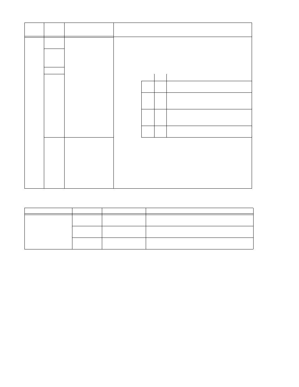
S3
S3-1
(LSB)
Function established
by S3-5
S3-5 determines the function of S3-1 through S3-4:
S3-2
S3-5 = 1:
S3-1: Voltage mode (1) or Current mode (0)
S3-2: Analog Input ON (1) or Analog Input OFF (0) Analog
input ON enables pin 11 of the I/O port.
S3-3
S3-3 and S3-4 determine limits upon power-up:
S3-4
(MSB)
S3-4 S3-3 Description
0
0
Analog External Protection limits enabled (see
PAR. 3.4.2)
0
1
Digital –V and –C Prot Max (Internal) set to
max. +V and +C Protect Max (Internal) set to
min. (box).
1
0
Digital +V and +C Prot Max (Internal) set to
max. –V and –C Prot Max (Internal) set to min.
(box).
1
1
Digital ±V Prot Max and ±C Prot Max (Internal)
set to max.
S3-5
Establish
function of
S3-1 through S3-4
S3-5 = 0:
Setting S3-4 (MSB) through S3-1 (LSB) to 0 (off) [0000] estab-
lishes a special analog control configuration upon power-up:
Analog Input ON (main channel reference, pin 11 of Analog I/O
port enabled), limit channel references (pins 5, 6, 13 and 14 of
Analog I/O port) enabled and pin 2 of Analog I/O port enabled
(1 or open = voltage mode, 0 or short = current mode).
Setting S3-4 (MSB) through S3-1 (LSB) to 1 [0001] to 15
[1111], restores custom configuration previously saved in
selected location 1 to 15. (See PAR. 3.5.7)
TABLE 2-3. IEEE 1118 CONNECTOR INPUT/OUTPUT PIN ASSIGNMENTS
CONNECTOR
PIN
SIGNAL NAME
FUNCTION
IEEE 1118 (BITBUS)
PORT
(connector A1J4)
1, 3 (shorted)
CONTROL BUS “A”
IEEE 1118, referenced to pins 5, 8
(2-Wire Differential Interface)
5, 8 (shorted)
CONTROL BUS “B”
IEEE 1118, referenced to pins 1, 3
(2-Wire Differential Interface)
6
TERMINATOR
Connect to pin 5 or 8 to add an internal termination resistor
to first/last unit on the daisy chain.
TABLE 2-2. POWER-UP SETUP SWITCHES (CONTINUED)
SWITCH
(FIGURE
2-2)
SECTION
FUNCTION
DESCRIPTION