GW Instek GDS-800 Series User Manual User Manual
Page 10
GDS-800 Series Digital Storage Oscilloscope Operation Manual
10
Probe compensation
To display an undistorted waveform on an oscilloscope, the probe must be matched
to the individual input impedance of each vertical amplifier.
For this purpose a square wave signal with a very fast rise time and minimum
overshoot should be used, as the sinusoidal contents cover a wide frequency range.
The build-in compensation signal generator provides a square wave signal with a
very fast rise time, and frequency of approx. 1kHz from the output socket below the
LCD screen. As the square wave signals are used for probe compensation
adjustment, neither the frequency accuracy nor the pulse duty factor are of
importance and therefore not specified.
The output provides 2V
pp
±3% for 10:1 probe. When the Y deflection coefficient is set
to 50mV/div, the calibration voltage corresponds to a vertical display of 4 divisions
(10:1 probe).
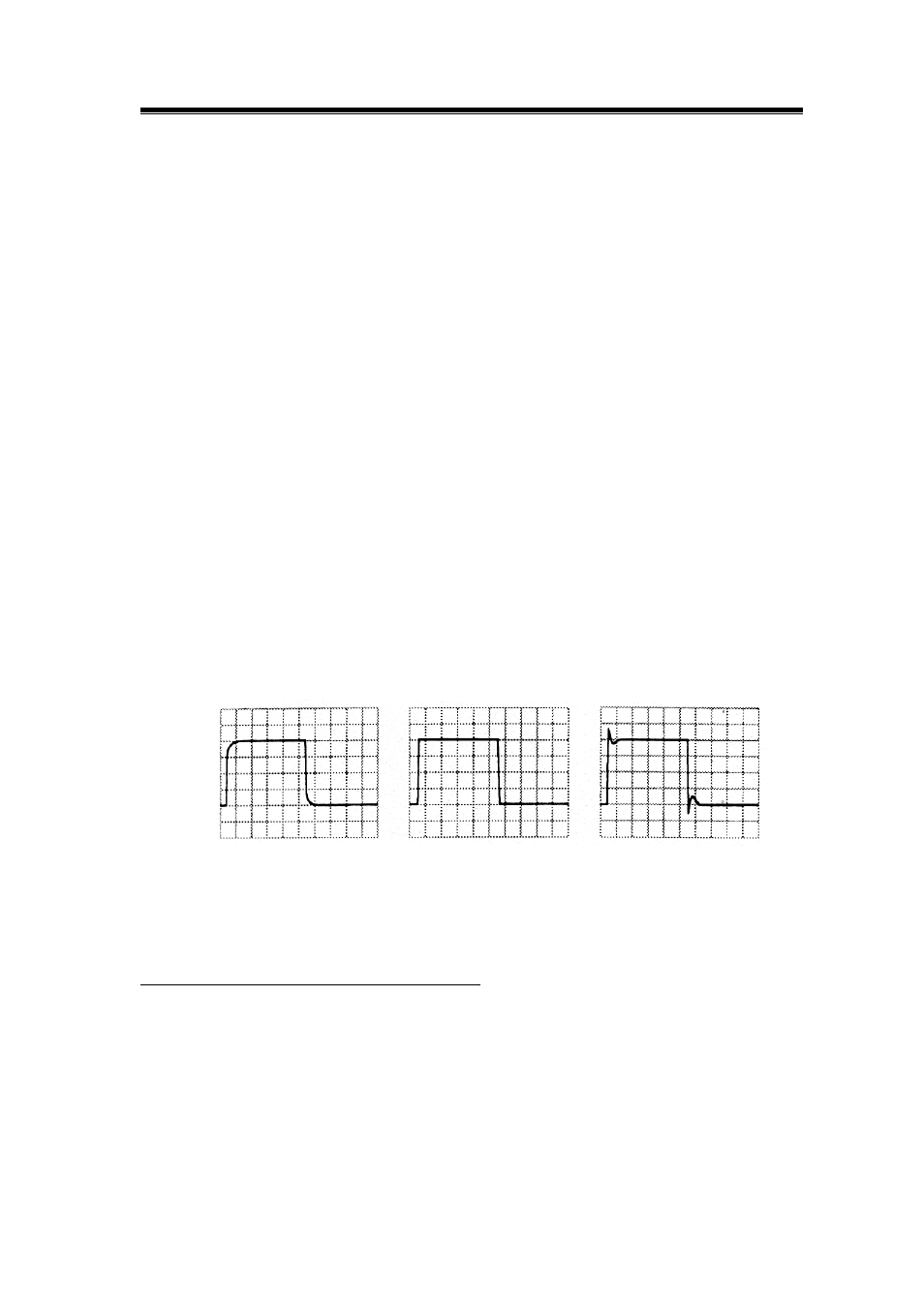
User checks the waveform indicated correct compensation (see Figure 3-2). If the
waveform indicates over or under compensation, use the alignment tool to adjust the
compensation.
incorrect
correct
incorrect
Figure 3-2: Probe compensations
For GDS-806S/C and GDS-810S/C only
GDS-806 and GDS-810 series provides a valuable “adjustable probe compensation
signal function”. The range for adjustable probe compensation signal is adjusted from
1kHz to 100kHz, 1kHz per step; and duty cycle is adjusted from 5% to 95%, 5% per
step. This function can satisfy user with the probe compensation easily and accurate.