6 paddle wheel flow sensor connections and setup – Aquametrix SHARK-120/240 Controllers User Manual User Manual
Page 12
Section 3 - Electrical Connections and Setup
Page 10
S
H
A
R
K
MULTI-PARAMETER CONTROLLER & ANALYZER USER’S MANUAL
Section 3 - Electrical Connections and Setup
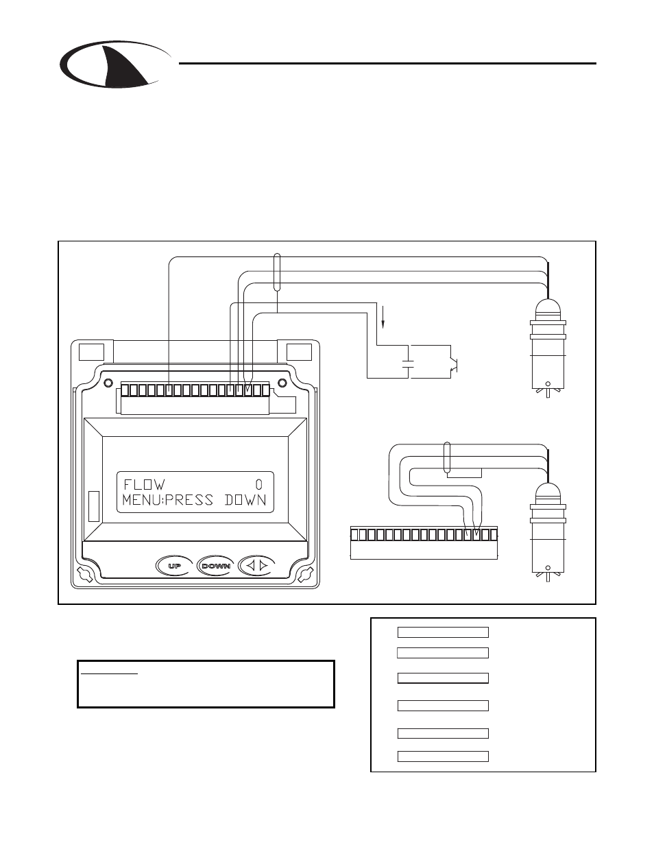
3.6 Paddle Wheel Flow Sensor connections and setup
P6
8
1 2 3 4
6
5
7
10
9
11 12 13 14 15 17
16
+12V (6)
GND (15)
(FLOW SWITCH INPUT) (13)
SIGNAL + (14)
SIGNAL - (GND) (15)
COLLECTOR
CONTACT
CLOSING THE FLOW SWITCH INPUT
TO GROUND WILL ZERO THE FLOW DISPLAY
DRY
OPEN
OR
9ma
+12V O.C.
FLOW SENSOR
EXTERNAL POWERED
FLOW SENSOR
SELF POWERED
16 17
15
14
13
12
11
9 10
8
7
5 6
4
3
2
1
SIGNAL - (15)
SIGNAL + (14)
SHIELD
SHIELD
SHIELD (15)
Figure 3.5 Connections for Flow Sensor
SETUP OF UNITS
OF VOLUME
SETUP OF UNITS
CALIBRATION FACTOR
ENTER FLOW SENSOR
SELECT FLOW METER
SEC. 7.6
OF TIME
SEC 7.5
SEC. 7.4
SEC. 7.1
TOTAL 0
TOTALIZER RESET
UNITS OF TIME
UNITS OF VOLUME
K FACTOR
METER SELECTION
RESET TOTALIZER
RUN MODE
TO ZERO
SEC 7.0
Note: Leave 4” to 6” slack for all wires connected to the ter-
minals of P6. Slack required so that wires do not interfere
with opening or closing of the front door.
Once connected, step through the LCD menus to select the
sensor in the order shown. The Sensor K factor (pulses per
U.S. Gallon) is usually printed on the side of the sensor or
on a label attached to the sensor cable.
The drawing shows the connnections for a typical paddle wheel flow sensor. The cable to the sensor
should not exceed 2000’ (600 meters).
The Shark controller also supports the use of an external “flow switch”. When the flow switch input is
grounded, either through a dry contact or solid state input, the flow display will be held at zero. This is
useful to ensure the flow reading remains locked at zero when conditions require it. The flow will start
reading again when the input is opened. If the flow switch function is not desired, simply leave it discon-
nected and the flow meter will read as normal.
Dwg# N104-37
CAUTION:
Always remove line power before unplugging or
plugging in the P6 connector