Flow - utilities menu - manual test mode 7.2 – Aquametrix SHARK-120/240 Controllers User Manual User Manual
Page 109
Flow - Utilities Menu - Manual Test Mode 7.2
Page 107
S
H
A
R
K
MULTI-PARAMETER CONTROLLER & ANALYZER USER’S MANUAL
Flow - Utilities Menu - Manual Test Mode 7.2
DOWN
DOWN
DOWN
UP
DOWN
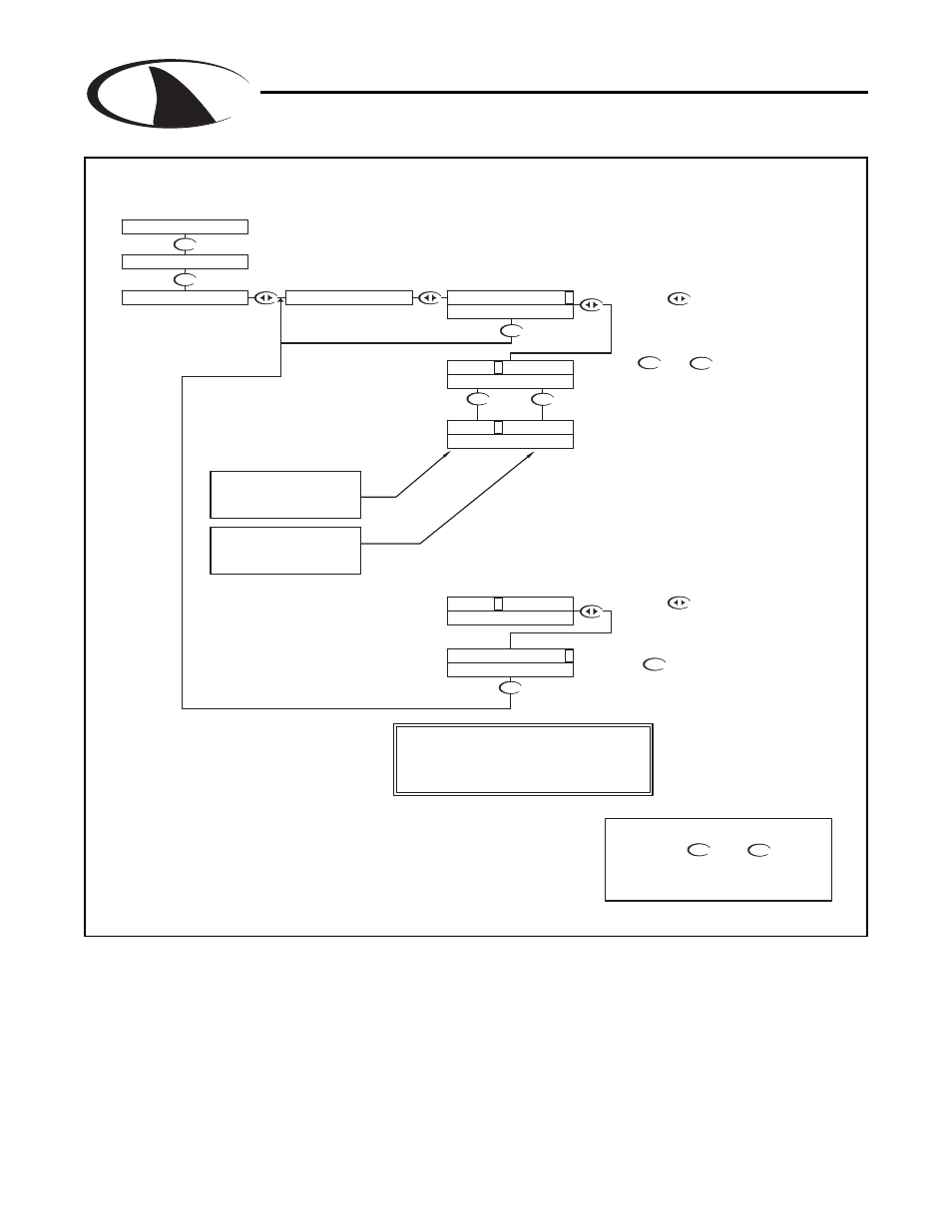
NOTE:
When the user exits the Manual Test Mode, the relays and
4-20mA outputs will remain in the Test Mode state until
the operator enters the run mode. The relays and outputs
will then revert back to the previous On-line state.
The CH1 4-20 mA output will
track the change in process
When a relay is energized, the
characters a,b,c will change to
upper case A,B,C
RUN MODE
UP
NOTE
PRESS THE AND KEYS
TOGETHER TO GO IMMEDIATELY BACK TO
RUN MODE
DOWN
Press the key once
which will move the cursor
over the least digit of the
simulated process value.
Use the and keys to change
the simulated process value.
Manual Test Mode is used to simulate a process reading
in order to verify the correct response of the outputs.
When in the Manual Test Mode, the outputs are no
longer placed on hold as they are when in the rest of the
menu.
Press the key once to
move the cursor to the RH side
of the display
Press the key to return to the
MANUAL TEST MODE menu
As well, Channel 1 4-20 ma output will also
follow the process value change. The actual
change will depend on how the CH1 output
was scaled in the OUTPUTS menus.
(See Section 4.18)
As the value is changed, the state of the relays
will change depending on their settings in the
OUTPUTS menu.
a/A - state of Relay A
b/B - state of Relay B
c/C - state of Alarm relay
DOWN
UP
DOWN
MANUAL TEST MODE
TOTAL 0
CALIBRATION
UTILITIES
TEST 65.00 GPM
>
TEST 65.0 0 GPM
>
a b c 14.4mA
a b c 14.4mA
TEST 65.0 0 GPM
>
TEST 50.0 0 GPM
>
TEST 50.00 GPM
>
a b c 12.0mA
a b c 12.0mA
a B c 14.4mA
DOWN