Aquametrix SHARK-120/240 Controllers User Manual User Manual
Page 10
Section 3 - Electrical Connections and Setup
Page 8
S
H
A
R
K
MULTI-PARAMETER CONTROLLER & ANALYZER USER’S MANUAL
Section 3 - Electrical Connections and Setup
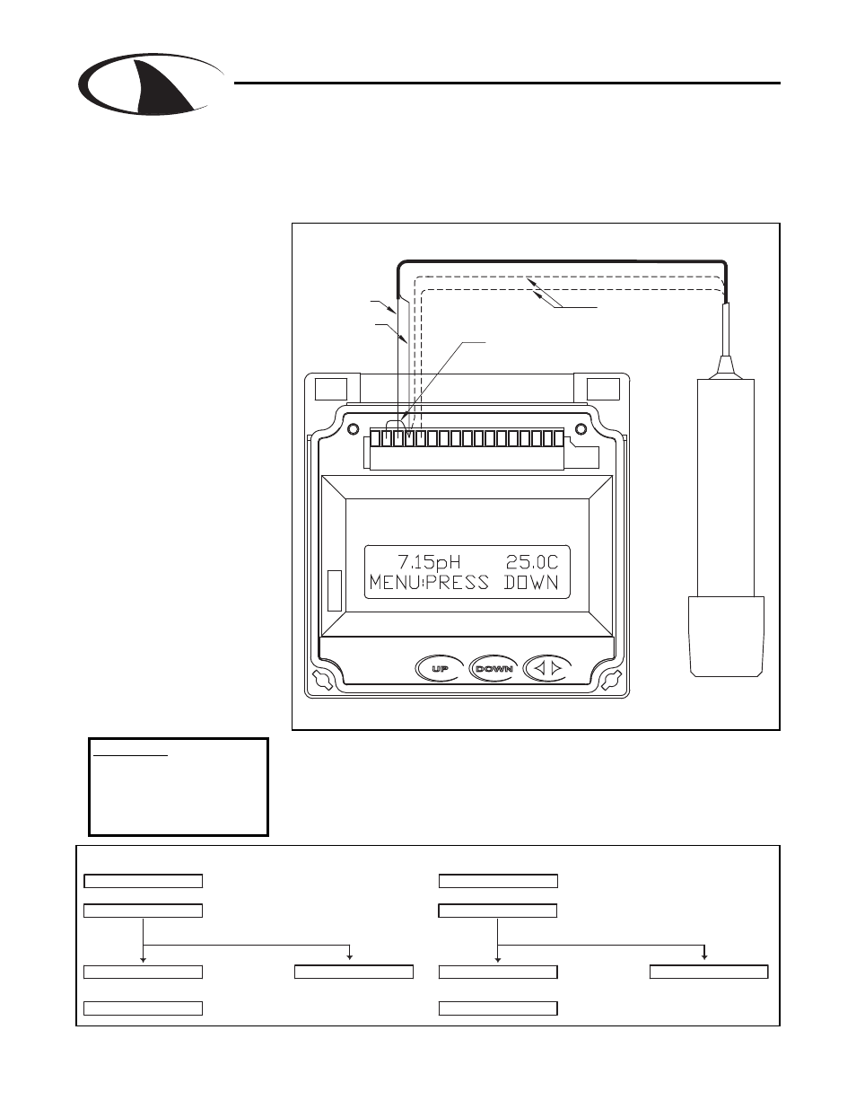
3.4 pH or ORP Combination Probe connections and setup
The drawing shows the connections for the Aquametrix Combination probe. The cable should be run in
a conduit separate from AC power wires, and via a separate conduit hole. The cable length should not
exceed 10 feet (3 meters).
These wires are only
present with 4-wire
combination probe.
JUMPER 2-4 MUST BE
INSTALLED FOR
COMBINATION PROBE
(CUSTOMER SUPPLIED)
COAX SHIELD (4)
COAX CENTER (3)
WHITE (5)
GREEN (4)
P6
8
1 2 3 4
6
5
7
10
9
11 12 13 14 15 17
16
COMBINATION
pH or ORP PROBE
Fig. 3.3 Connections for the 2 and 4 wire Combination Probe
SEC. 5.8
SEC. 5.5
SEC. 5.1
ORP PROBE
SELECT COMBINATION PROBE
SELECT ORP METER
MANUAL CALIBRATE
PH PROBE
MANUAL CALIBRATE
SELECT PH METER
SELECT COMBINATION PROBE
SEC. 4.1
SEC. 4.6
SEC. 4.7
SEC 4.10
MANUAL PROBE
TEMPERATURE SETUP
DISABLE TEMPERATURE
SEC 5.10
DISPLAY
MANUAL CAL PH
METER SELECTION
PROBE SELECT
7.15pH 25.0C
T.COMP OVERRIDE
7.15pH 25.0C
PROBE SELECT
METER SELECTION
MANUAL CAL PH
T.DISP OVERRIDE
RUN MODE
TWO WIRE PROBE WITH NO TEMP SENSOR
TWO WIRE PROBE WITH NO TEMP SENSOR
RUN MODE
ORP
pH
Once connected, step throught the LCD menus to select the probe in the order
shown. The first two steps may be skipped if the meter is already configured for
a Combination Probe. If a two wire pH probe is used, which has no temperature
sensor, ensure that the Temp. Comp. Override is set to same temperature as
the buffer before calibrating. If a two wire ORP probe is used, you can blank the
Temp display with the T DISP OVERRIDE menu.
The
2 wire version has no
temperature sensor and is
connected via a coaxial wire.
In a pH meter, the user
should set the
T COMP
OVERRIDE
menu to
ON
(Section 4.11) and adjust the
temperature setting to the
actual probe temperature.
In an ORP meter, the user
should set the
T.DISP OVER-
RIDE to ON (Section 5.10) to
blank the temperature reading
on the display.
The
4 wire version has two
additional wires for the probe
internal temperature sensor.
Ensure that the
T COMP
OVERRIDE or T.DISP
OVERRIDE is OFF.
Note: Leave 4” to 6” slack for
all wires connected to the ter-
minals of P6. Slack required
so wires do not interfere with
opening/closing of front door.
Dwg# N104-35
CAUTION:
Always remove line
power before unplugging
or plugging in the P6
connector