2 normal operation, 1 starting operation, 2 corrective actions in case of failure – Yokogawa GD40 Gas Density Detector User Manual
Page 51: Normal operation -8 3.2.1, Starting operation -8, Corrective actions in case of failure -8
<3. Operation>
3-8
IM 11T3E1-01E
3.2
Normal Operation
In normal operation, there is no need for working with the GD402 analyzer except when calibrat-
ing it. Unless there is any failure found, carry out maintenance, inspection, and so on at the same
time the analyzer is calibrated. The analyzer is designed to prohibit you from calibrating it or set-
ting each parameter unless you have entered the password (XXX).
(See section “4.2 Setting Lists”.)
3.2.1
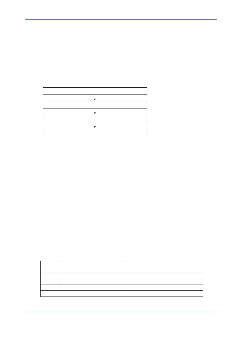
Starting Operation
Follow the procedure below to start operation.
Completing these steps return to the
Turn on the external power switch.
Set the operating parameters.
Calibrate the analyzer for correct zero and span setpoints.
F0307.ai
The following details the operations required in this procedure.
(1) The analyzer, when turned on, indicates the density value. See Figure 5.2, 6.3 or 7.3 for the
operations used to change to the required unit of density.
(2) Set the relevant operating parameters by checking and modifying their default values in
order to meet individual operating requirements.
(3) Supply the zero and span gases to check readings. If the readings contain errors, the ana-
lyzer must be calibrated. For details on calibration, see Chapter 8, 9 or 10.
(4) When calibration is complete, the analyzer returns to the
3.2.2
Corrective Actions in Case of Failure
If the GD402 analyzer senses a failure, it sends out a FAIL contact output signal through ter-
minals 18 and 19. In such a case, the output signal is held at either the value held immediately
before or at the preset value for each setting.
The message field indicates the type of error by the error code. Should a failure occur, check the
nature of the failure and take corrective action without delay. Table 3.1 summarizes the numeric
codes of errors that may occur in the measurement mode. For details on each type of error, see
Table 11.2 on page 11-4.
Table 3.1 Errors that May Occur in the Measurement Mode
Error No.
Nature of Failure
Corrective Actions
Err. 01
Sensor oscillation shutdown
Reset the power and contact service personnel.
Err. 02
Faulty oscillation frequency of sensor
Reset the power and contact service personnel.
Err. 03
Sensor’s failure to detect temperature
Contact service personnel.
Err. 04
Failure in A/D converter
Contact service personnel.
Err. 05
Failure in memory
Contact service personnel.