5 cable wired to gd40 detector, Cable wired to gd40 detector -19, 5 cable wired to gd40 detector – Yokogawa GD40 Gas Density Detector User Manual
Page 42
<2. Installation, Wiring and Piping>
2-19
IM 11T3E1-01E
2.4.5
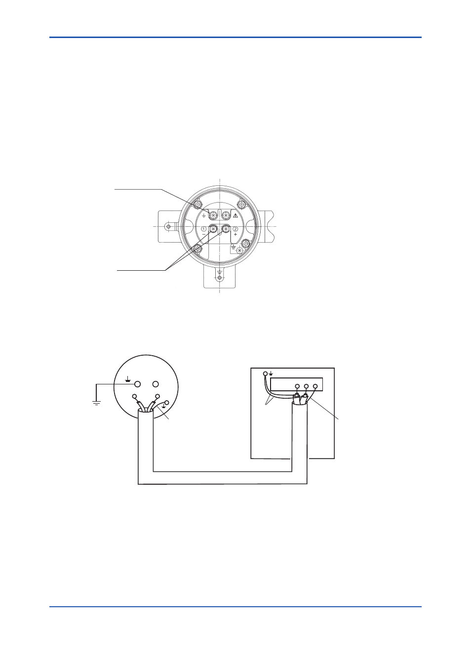
Cable Wired to GD40 Detector
The cable wired to the GD40 detector comes from the GD402 converter. Use a shielded cable
of 10 to 13.5 mm in finished outer diameter that suits the dedicated cable gland. Wire the cable
through the cable gland, being careful not to connect the cable with the wrong polarities. Attach
M4 crimp terminals to the ends of the core wires (see Figure 2.14). Connect the shielding wire to
terminal 13 on the converter (see Figure 2.12). When crimping the terminals, use tools that fit the
terminals.
If a malfunction occurs and it is assumed to be due to noise, use a double-shielded cable (for ex-
ample, the cable with Yokogawa’s Model GDW-L ). Connect the outer shielding wire to ter-
minal 13 on the converter and the other end of the wire to the grounding terminal on the detector.
Connect the inner shielding wires to the grounding terminal on the converter (see Figure 2.17).
Terminals for
wiring to converter
F0219.ai
Class A
grounding terminal
Figure 2.15 Configuration of Detector Terminals
11 12 13
Outer shielding wire
Class A
grounding
terminal
Do not connect the inner
shielding wires here.
Inner shielding
wires
Outer shielding
wire
GD40T, V, R
Detector
GD402G, T, V, R
Converter
F0220.ai
Class A
grounding
Figure 2.16 Connection Between Detector and Converter When Using a Double-Shielded Cable