4 cables wired to contact i/os, Cables wired to contact i/os -18 – Yokogawa GD40 Gas Density Detector User Manual
Page 41
<2. Installation, Wiring and Piping>
2-18
IM 11T3E1-01E
2.4.4
Cables Wired to Contact I/Os
The contact I/Os of the GD402 converter comprise the start-of-calibration contact (input), the
FAIL, ALARM and MAINTENANCE contacts, and the contacts for operating the solenoid valves
for span and zero calibrations. Choose the type of cables for a group of calibration-purpose con-
tacts and for a group of other contacts separately.
For wiring to the calibration contact output, use a cable of 8 to 16 mm in finished outer diameter
and 1.25 mm
2
minimum in thickness. For wiring to other contacts, use a cable of 8 to 16 mm in
finished outer diameter and 0.13 to 1.25 mm
2
in thickness, while choosing the number of core
wires depending on the number of contacts used.
Since the contact outputs are voltage-free, driving such devices as alarm lamps requires a sepa-
rate power supply. For the contact input (start of calibration), provide a voltage-free signal.
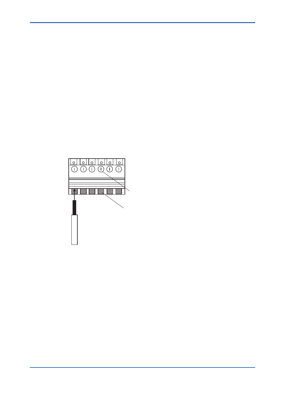
Wire the cables as instructed below:
(1) Use cables 0.13 to 1.25 mm
2
thick. Treat the cable ends by stripping back the core wires to 7
mm from the end (see Figure 2.14).
(2) Wire the cables to their respective given terminals on the block, being careful not to mistake
one terminal for another. For terminal numbers assigned to the respective contacts I/Os, see
Figure 2.12.
Loosen the terminal screws, insert the stripped ends of the core wires into the terminals, and
fasten the screws to fix the cables. (The appropriate tightening torque is 0.4 N·m)
Cable
F0218.ai
Cable inlet
Tightening screw
Terminal
Figure 2.14 Connection between terminal and cable