3 cables wired to outputs, Cables wired to outputs -17 – Yokogawa GD40 Gas Density Detector User Manual
Page 40
<2. Installation, Wiring and Piping>
2-17
IM 11T3E1-01E
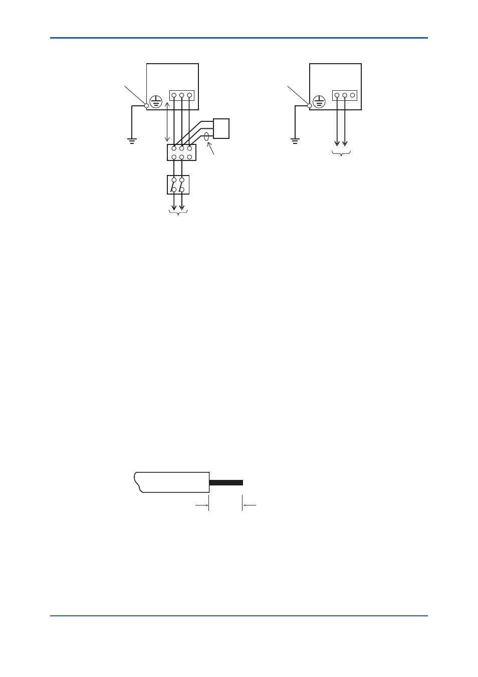
100 to 240 V AC
50/60Hz
Surge Protector
GD402 Converter
100-240 V AC type
SUPPLY
L N G
Green cable
1m
max
External circuit breaker
Rating: 5 A
Case-grounding
terminal
Case-grounding
terminal
SUPPLY
+ - G
24 V DC
F0216.ai
GD402 Converter
24 V DC type
Use IEC947-1 or IEC947-3 compliant product.
Terminal box
*
1
*
1 Surge protector and terminal box should be installed in order to meet
the requirements of CE marking.
*
1
Figure 2.12 Cables Wired to Power Supply
2.4.3
Cables Wired to Outputs
These cables are used to transmit 4-20 mA DC signals and carry out BRAIN communication.
Use shielded cables of 8 to 16 mm in finished outer diameter and 0.75 mm
2
minimum in thick-
ness (or a two-core shielded cable for single output).
Wire the cables as instructed below:
(1) Use cables that are 0.75 to 2.5 mm
2
thick. Treat the cable ends by stripping the core wires
back 7 mm (see Figure 2.14).
(2) Wire the cable for output 1 to terminals 3 and 4 on the block and the cable for output 2 to
terminals 5 and 6 on the block. Beware of the correct polarities. Note that only terminals 3 and
4 (output 1) are effective for BRAIN communication.
Loosen the terminal screws, insert the stripped ends of the core wires into the terminals, and
fasten the screws to fix the cables.
(3) Ground the shielding wire at a given terminal on the converter; do not ground the other end of
the cable. (The appropriate tightening torque for the internal wiring terminals is 0.4 N·m.)
7mm
F0217.ai
Figure 2.13 Examples of Treatment on Cable End Wired to the Converter