2 display configuration – Yokogawa Integral Oxygen Analyzer ZR202 User Manual
Page 78
IM 11M12A01-05E
7-5
7. Startup
7.4.2
Display Configuration
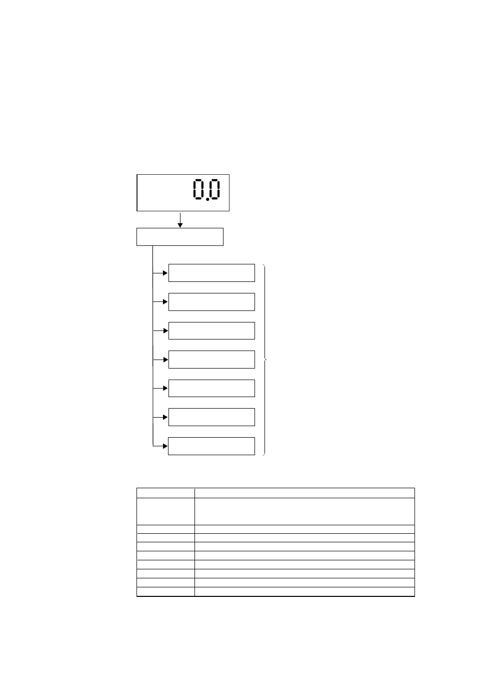
The parameter codes provided for the equipment are used to control the equipment
display panels (see below). By selecting appropriate parameter codes, you can conduct
calibration and set operation parameters. Figure 7.4 shows the configuration of display
items. The parameter codes are listed in groups of seven; which are briefly described in
Table 7.2.
To enter parameters, you first need to enter the password.
Touch the [ >] key and [ ENT ] key at same time to revert to the main screen.
F7.4E.EPS
Group G setup display
Basic panel display
Password entry display
Group A setup display
Group B setup display
Group C setup display
Parameter code
selection display
Group D setup display
Group E setup display
Group F setup display
%
Figure 7.4 Display Configuration
Table 7.2 Display Functions
Basic panel
Displays the oxygen concentration in normal operation, or displays the detector
heater temperature while warming up. If an error or alarm arises,
the corresponding error or alarm number appears.
Password entry
Enters the password for the parameter code selection display.
Group A setup
Displays detailed data, such as the cell voltage or temperature.
Group B setup
Sets and performs calibration and blowback.
Group C setup
Sets analog output.
Group D setup
Sets an alarm.
Group E setup
Sets the input and output contacts.
Group F setup
Selects the type of equipment and sets the parameters for computation.
Group G setup
Performs the current-loop or contact checks.
T7.2E.EPS
Display
Function and item to be set