3 wiring power and ground terminals, 1 wiring for power line, 2 wiring for ground terminals – Yokogawa Integral Oxygen Analyzer ZR202 User Manual
Page 68: Wiring procedure -6, Wiring for contact input -7, Cable specifications -7
IM 11M12A01-05E
5-5
5. Wiring
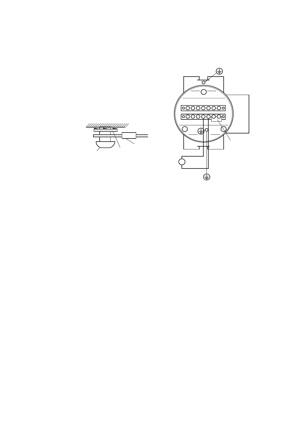
5.3 Wiring Power and Ground Terminals
Wiring for supplying power to the analyzer and grounding the equipment.
1
2
C
DO
DO
DI
1
2
FG
L
N
G
FG
+
-
AO
~
100~240 V AC
50/60 Hz
F5.5E.EPS
Jumper plate
Grounding to the ground terminal
on the equipment case
Equipment case
Lock washer
Crimp contact of
the grounding line
Grounding
terminal
Ground
Figure 5.5 Power and Grounding Wiring
5.3.1
Wiring for Power Line
Connect the power wiring to the L and N terminals of the equipment. For a three-core
cable, ground one core appropriately. Proceed as follows:
(1) Use a two-core or three-core shielded cable.
(2) M4 screws are used for the terminals. Use crimp-on terminals appropriate for M4
terminal screws for cable connections.
5.3.2
Wiring for Ground Terminals
The ground wiring of the analyzer should be connected to either the ground terminal of
the equipment case or the terminal inside of the equipment. Proceed as follows:
(1) Keep the ground resistance of 100V or less (JIS Class D grounding).
(2) When connecting the ground wiring to the ground terminal of the equipment case, be
sure that the lock washer is in contact with the case surface (see Figure 5.5.).
(3) Ensure that the jumper plate is connected between the G terminal and the FG
terminal of the equipment.
(4) The size of external ground screw thread is M4. Each cable should be terminated
corresponding crimp-on terminals.