2 piping for the calibration gas, 3 piping for the reference gas, Piping for the calibration gas -4 – Yokogawa Integral Oxygen Analyzer ZR202 User Manual
Page 60: Piping for the reference gas -4
IM 11M12A01-05E
4-4
4.2.2 Piping for the Calibration Gas
This piping is to be installed between the zero gas cylinder and the ZA8F flow setting
unit, and between the ZA8F flow setting unit and the ZR202G analyzer.
The cylinder should be placed in a calibration gas unit case or the like to avoid any
direct sunlight or radiant heat so that the gas cylinder temperature does not exceed 408 C.
Mount a pressure regulator (recommended by YOKOGAWA) on the cylinder.
Mount a stop valve or the check valve (recommended by YOKOGAWA) on the nipple
(commercially available) at the calibration gas inlet of the equipment as illustrated in
Figure 4.8. (The check valve or the stop valve may have been mounted on the equip-
ment when shipped.) Connect the flow setting unit and the analyzer to a 6 mm (O.D.) 3
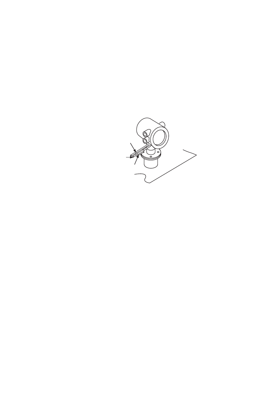
4 mm (I.D.) (or nominal size 1/4 inch or larger) stainless steel pipe.
F4.8E.EPS
Stop valve or check valve
Piping for the reference gas
6 mm (O.D.) by 4 mm (I.D.)
stainless steel pipe
Piping for the calibration gas
6 mm (O.D.) by 4 mm (I.D.)
stainless steel pipe
Figure 4.8 Piping for the Calibration Gas Inlet
4.2.3 Piping for the Reference Gas
Reference gas piping is required between the air source (instrument air) and the flow
setting unit, and between the flow setting unit and the analyzer.
Insert the air set next to the flow setting unit in the piping between the air source and
the flow setting unit.
Use a 6 mm (O.D.) 3 4 mm (I.D.) (or nominal size 1/4 inch or larger) stainless steel
pipe between the flow setting unit and the analyzer.