1 terminals for the external wiring, 2 wiring, Wiring procedure -4 – Yokogawa Integral Oxygen Analyzer ZR202 User Manual
Page 65: Wiring power and ground terminals -5, Figure 5.1 terminals for external wiring, Figure 5.2 wiring connection
IM 11M12A01-05E
5-2
5.1.1
Terminals for the External Wiring
Remove the terminal cover on the opposite side of the display to gain access to the
external wiring terminals.
1
2
C
DO
DO
DI
1
2
L
N
FG
+
-
AO
G FG
F5.1E.EPS
Figure 5.1 Terminals for External Wiring
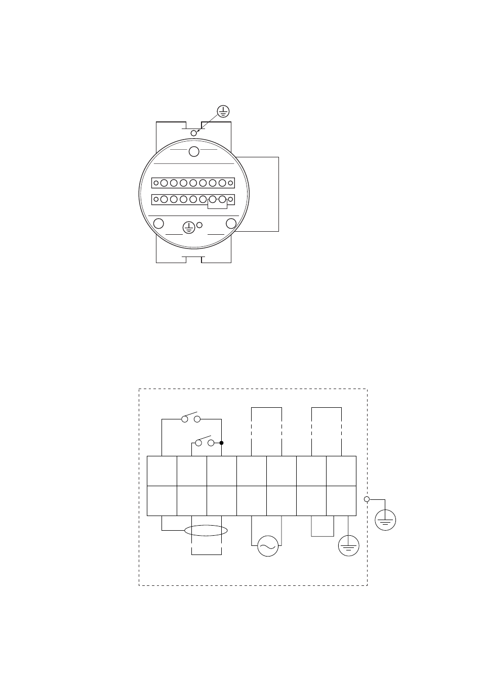
5.1.2
Wiring
Make the following wiring for the equipment. It requires a maximum of four wiring
connections as shown below.
(1) Analog output signal
(2) Power and ground
(3) Contact output
(4) Contact input
1
DI-1
2
DI-2
3
DI-C
4
DO-1
5
DO-1
6
DO-2
7
DO-2
8
FG
9
AO
(+)
10
AO
(-)
11
L
12
N
13
G
14
FG
F5.2E.EPS
Contact input 1
Contact output 2
Contact output 1
Analog output
4-20 mA DC
100 to 240 V AC,
50 or 60 Hz
Digital output
Contact input 2
The protective grounding for the analyzer shall be connected either the protective
ground terminal in the equipment or the ground terminal on the case.
Standard regarding grounding: Ground to earth, ground resistance: 100V or less.
Figure 5.2 Wiring Connection