2 probe insertion, Probe insertion -2, Caution – Yokogawa Integral Oxygen Analyzer ZR202 User Manual
Page 42
IM 11M12A01-05E
3-2
3.1.2 Probe Insertion
CAUTION
• The outside dimension of detector may vary depending on its options. Use a pipe that
is large enough for the detector. Refer to Figure 3.1 for the dimensions.
• If the detector is mounted horizontally, the calibration gas inlet and reference gas inlet
should face downwards.
• When using the detector with pressure compensation, ensure that the flange gasket
does not block the reference air outlet on the detector flange. If the flange gasket
blocks the outlet, the detector cannot conduct pressure compensation. Where neces-
sary, make a notch on the flange gasket. Confirm the outside dimensions of the
detector in Chapter 3.6 before installation.
• The sensor (zirconia cell) at the probe tip may deteriorate due to thermal shock if
water drops are allowed to fall on it, as it is always at high temperature.
(1) Do not orient the end of the detector probe upwards.
(2) If the probe length is 2.5 meters or longer, mount the detector vertically (no more
than a 58 tilt).
(3) Position the detector probe perpendicular to the measurement gas flow, or point the
tip downstream.
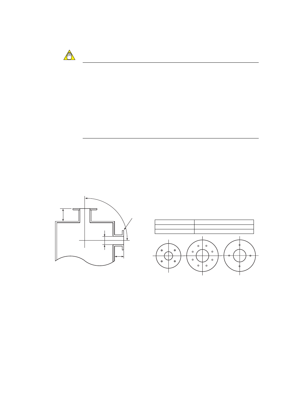
Figure 3.1 illustrates an example of the probe insertion.
100 mm
100 mm
F3.1E.EPS
(vertical)
Bounds of the probe
insertion hole location
Flange corresponds
to the detector size
(horizontal)
(Note)
When the detector with the ZH21B dust protector is used, provide a 80-mm dia.
or more flange, as shown in the above figure.
When using the detector with pressure compensation, ensure that the flange
gasket does not block the reference air outlet on the detector flange. If the flange
gasket blocks the outlet, the detector cannot perform pressure compensation.
Where necessary, make a notch in the flange gasket. Confirm the outside
dimensions of the detector in Chapter 3.6 before installation.
*1 Note
Type
Outside diameter of detector
Standard
50.8 mm in diameter (Note)
With dust protector
80 mm in diameter or longer (Note)
Four-hole flange Eight-hole flange JIS flange
(the detector with
dust protector)
*1
Figure 3.1 Example of Probe Insertion