2 setting output contact, Input contact settings -18, Warning – Yokogawa Integral Oxygen Analyzer ZR202 User Manual
Page 111
IM 11M12A01-05E
8-14
8.4.2
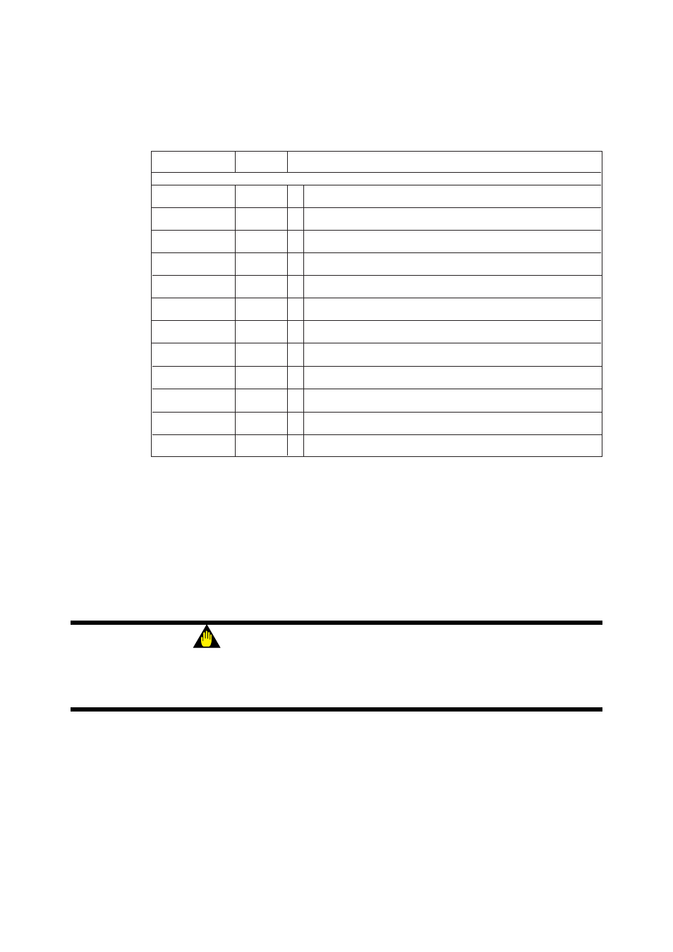
Setting Output Contact
Set the output contacts following Table 8.9.
Table 8.9 Parameter Codes for Output Contact Setting
Set item
Parameter
Set value
code
Output contact 1
Operation
E10
0 Operated in closed status. (Normally deenergized)
1 Operated when open. (Normally energized) (Note 1)
Error
E20
0 Not operated if an error occurs.
1 Operated if an error occurs.
High-high limit alarm
E21
0 Not operated if a high-high limit alarm occurs.
1 Operated if a high-high limit alarm occurs. (Note 2)
High-limit alarm
E22
0 Not operated if a high-limit alarm occurs.
1 Operated if a high-limit alarm occurs. (Note 2)
Low-limit alarm
E23
0 Not operated if a low-limit alarm occurs.
1 Operated if a low-limit alarm occurs.
Low-low limit alarm
E24
0 Not operated if a low-low limit alarm occurs.
1 Operated if a low-low limit alarm occurs. (Note 2)
Maintenance
E25
0 Not operated during maintenance.
1 Operated during maintenance (see Section 8.2.1).
Calibration
E26
0 Not operated during calibration.
1 Operated during calibration (see Section 8.2.1).
Range change
E27
0 Not operated when changing ranges.
1 Operated when changing ranges. (Note 3)
Warm-up
E28
0 Not operated during warming up.
1 Operated during warming up.
Calibration-gas
E29
0 Not operated while a calibration-gas pressure drop contact is being closed.
pressure drop
1 Operated while a calibration-gas pressure drop contact is being closed. (Note 4)
Unburnt gas
E32
0 Not operated while a unburnt gas detection contact is being closed.
detection
1 Operated while a unburnt gas detection contact is being closed. (Note 5)
T8.10E.EPS
Note 1: Output contact 2 remains closed.
Note 2: For the high-high alarm, the concentration alarm must be preset (see
Section 8.3).
Note 3: Range change answer-back signal. For this action, the range change must be
preset during the setting of input contacts (Section 8.5).
Note 4: Calibration gas pressure decrease answer-back signal. Calibration gas pressure
decrease must be selected beforehand during the setting of input contacts.
Note 5: Non-combusted gas detection answer-back signals. “Non-combusted gas”
detection must be selected during the setting of input contacts.
WARNING
• Output contact 2 is linked to the detector’s heater power safety switch. As such, if
output contact 2 is on, the heater power stops and an Error 1 (cell voltage abnormal)
or Error 2 (heater temperature abnormal) occurs.