Yokogawa Integral Oxygen Analyzer ZR202 User Manual
Page 53
IM 11M12A01-05E
3-13
3. Installation
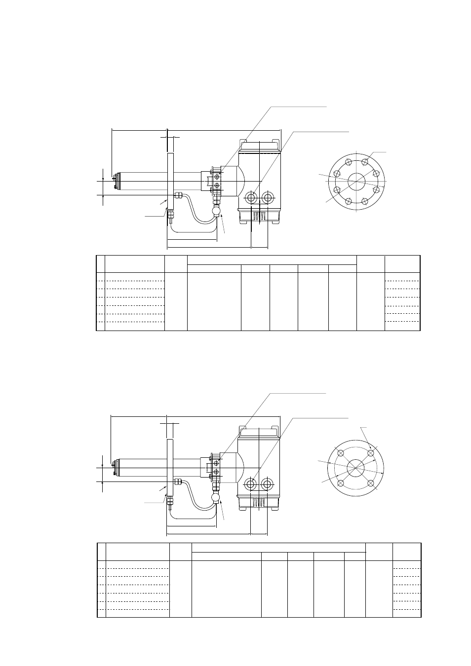
6. DIN PN10 DN100
d
ZR202G-hhh-h-G-P
Flange : DIN PN10 DN100 SUS304
15663
L
25664
49
34264
25
t
F3.23E.EPS
PIPING:A
PIPING
:B
45
Rc1/4 or 1/4NPT
Reference air inlet
2-G1/2, 2-1/2NPT etc.
Cable connection port
Stop Valve
Flange
Reference gas outlet
Flange
Model, Code
Specification
A
B
C
t
Weight
(kg)
ZR202G-040-h-G
ZR202G-070-h-G
ZR202G-100-h-G
ZR202G-150-h-G
ZR202G-200-h-G
ZR202G-250-h-G
ZR202G-300-h-G
400
700
1000
1500
2000
2500
3000
DIN PN10 DN100
SUS304
220
180
8-[18
20
L
PIPING
B
Approx. 11
Approx. 13
Approx. 14
Approx. 15
Approx. 17
Approx. 19
Approx. 21
[A
C
[B
Flange
7. JIS 5K 65 FF
d
ZR202G-hhh-h-K-P
Flange : JIS 5K 65 FF SUS304
15663
L
25664
49
34264
25
t
[A
C
[B
Flange
F3.24E.EPS
PIPING:A
PIPING
:B
33
Rc1/4 or 1/4NPT
Reference air inlet
2-G1/2, 2-1/2NPT etc.
Cable connection port
Stop Valve
Flange
Reference gas outlet
Model,Code
Specification
Flange
A
B
C
t
Weight
(kg)
ZR202G-040-u-K
ZR202G-070-u-K
ZR202G-100-u-K
ZR202G-150-u-K
ZR202G-200-u-K
ZR202G-250-u-K
ZR202G-300-u-K
400
700
1000
1500
2000
2500
3000
JIS 5K 65 FF
SUS304
155
130
4-
[
15
14
L
PIPING
A
Approx, 8
Approx. 9
Approx. 10
Approx. 12
Approx. 14
Approx. 15
Approx. 17