2 wiring for analog output, 1 cable specifications, 2 wiring procedure – Yokogawa Integral Oxygen Analyzer ZR202 User Manual
Page 67: Wiring for ground terminals -5, Wiring for contact output -6, Cable specifications -6, Caution
IM 11M12A01-05E
5-4
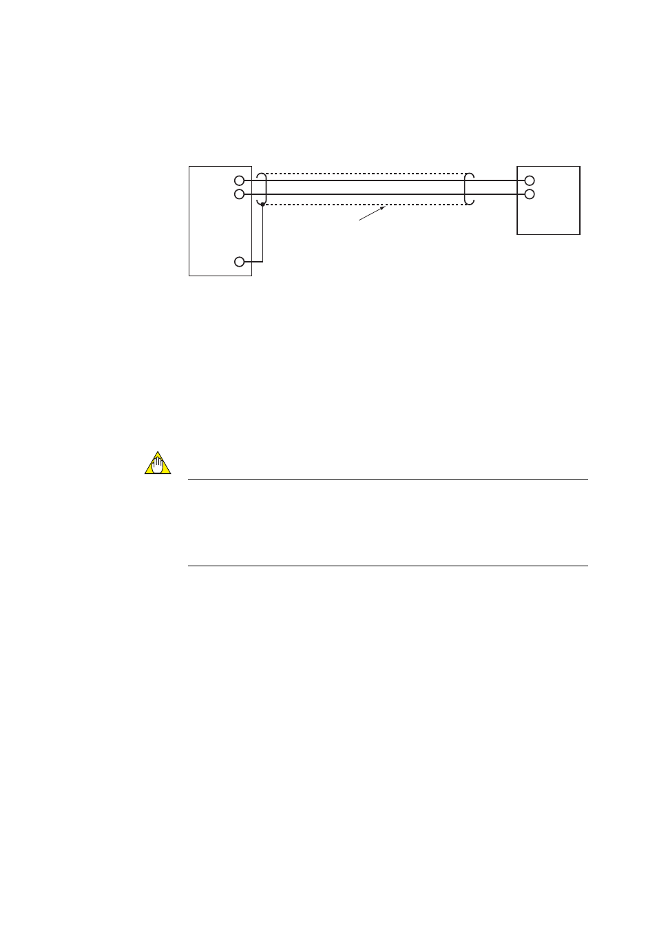
5.2 Wiring for Analog Output
This wiring is for transmitting 4 to 20 mA DC output signals to a device, e.g. recorder.
Maintain the load resistance including the wiring resistance of 550V or less.
+
-
AO(+)
AO(
-
)
FG
F5.4E.EPS
Shielded cables
Analyzer
Receiver
Figure 5.4 Wiring for Analog Output
5.2.1
Cable Specifications
Use a 2-core shielded cable for wiring.
5.2.2
Wiring Procedure
(1) M4 screws are used for the terminals. Use crimp-on terminals appropriate for M4
terminal screws for cable connections. Ensure that the cable shield is connected to
the FG terminal of the equipment.
(2) Be sure to connect (+) and (2) polarities correctly.
CAUTION
• Before opening the detector cover, loosen the lock screw. If the screw is not loosened
first, the screw will damage the cover and the terminal box will require replacement.
When opening and closing the cover, remove any sand particles or dust to avoid
gouging the thread.
• After screwing the cover on the equipment body, secure it with the lock screw.