3 piping for system configuration 3, Piping for system configuration 3 -5, Figure 4.9 piping for system 3 – Yokogawa Integral Oxygen Analyzer ZR202 User Manual
Page 61
IM 11M12A01-05E
4-5
4. Piping
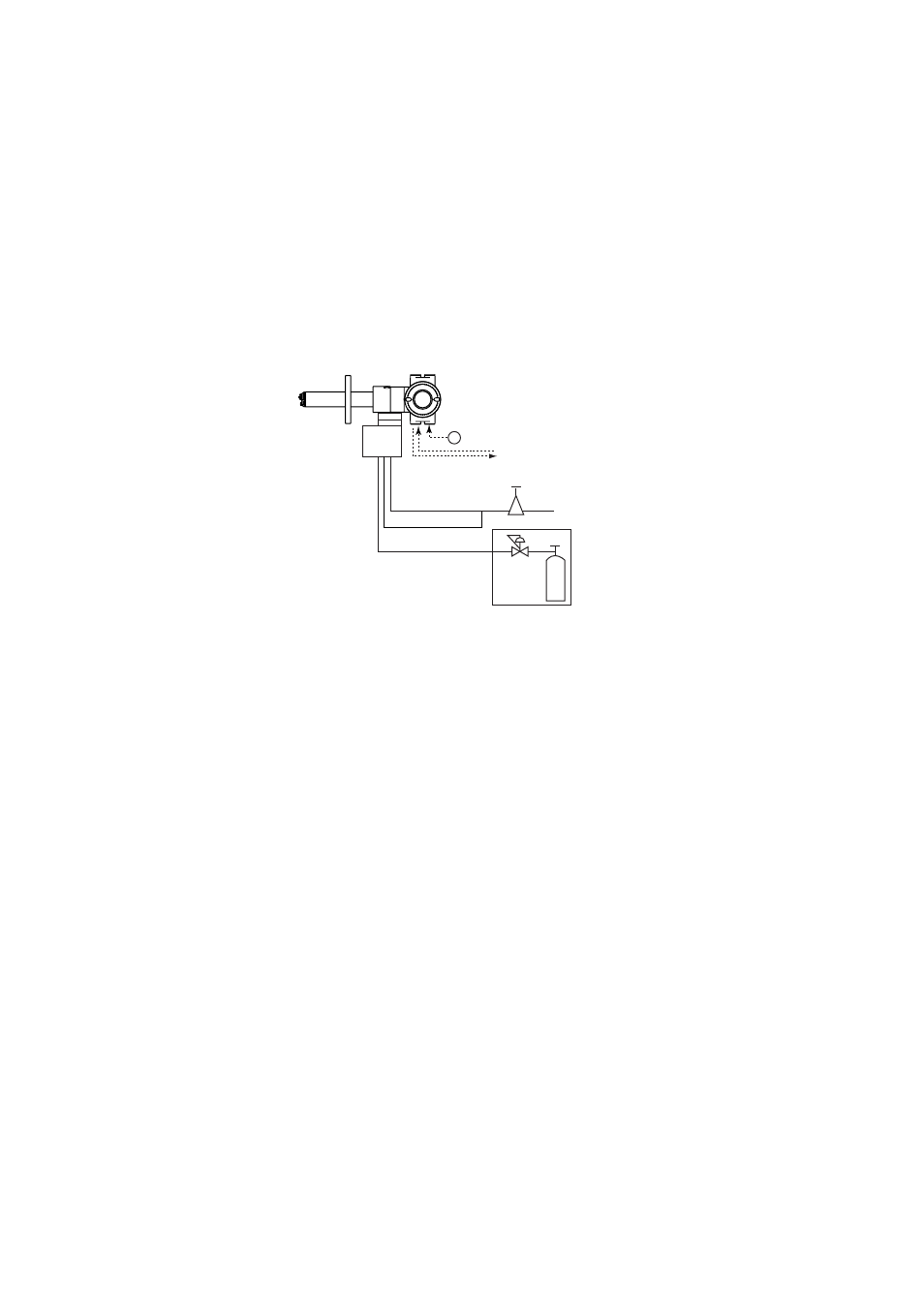
4.3 Piping for System Configuration 3
Piping in System 3 is illustrated in Figure 4.9. In System 3, calibration is automated;
however, the piping is basically the same as that of System 2. Refer to Section 4.2.
Adjust secondary pressure of both the air set and the zero gas regulator so that these two
pressures are approximately the same. The flow rate of zero and span gases (normally
instrument air) are set by individual needle valve. After installation and wiring, check
the calibration contact output (see Sec. 7.9.2), and adjust zero gas regulator and calibra-
tion gas needle valve so that zero gas flow is within the permitted range. Next check
span gas calibration contact output and adjust air set so that span gas flow is within the
permitted range.
~
100 to 240 V AC
Auto Calibration unit
ZR20H
Reference gas
Calibration gas
Contact input
Analog output, contact output
Digital output (HART)
Air Set
Instrument air
Calibration gas
unit case
Calibration gas pressure regulator
Zero gas cylinder
F4.9E.EPS
Model ZR202G Integrated type Zirconia
High Temperature Humiddity Analyzer
Span gas
Figure 4.9 Piping for System 3