1 cable specifications, 2 connection to the detector – Yokogawa Single Channel Oxygen Analyzer System ZR22/ZR402 User Manual
Page 85
IM 11M13A01-02E
5-6
5.2.1
Cable Specifications
During operation of the process, the terminal box may get quite hot and may reach
temperatures of up to 150
Њ C. The cable may be exposed to even higher temperatures, so
be sure to use suitably heat-resistant cable.
Basically, PVC sheathed PVC insulated cable (six core) is used for this wiring. When
the ambient temperature of the detector exceeds 80
Њ C, install a terminal box, and
connect with the detector using six-piece 600V silicon rubber insulated glass braided
wire.
5.2.2
Connection to the Detector
To connect cables to the detector, proceed as follows:
(1) Mount conduits of the specified thread size or cable glands to the wiring connections
of the detector.
The detector may need to be removed in future for maintenance, so be sure to allow
sufficient cable length.
(2) If the ambient temperature at the location of wire installation is 80 to 150
Њ C, be sure
to use a flexible metallic wire conduit. If a non-shielded “ 600V silicon rubber
insulated glass braided wire “ is used, keep the wire away from noise sources to
avoid noise interference.
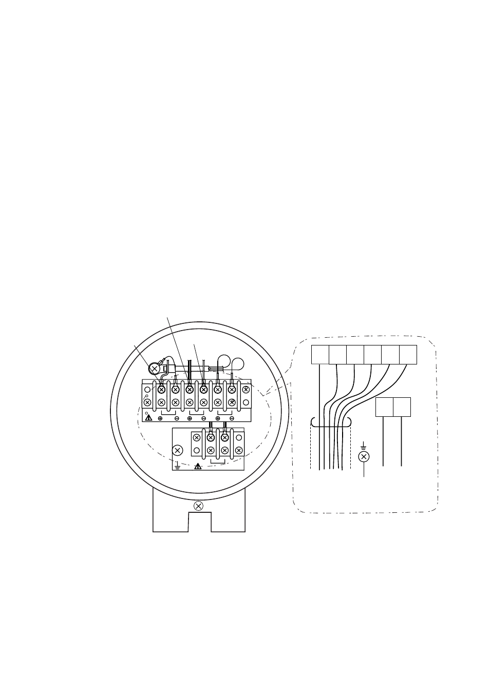
(3) Figure 5.5 shows the layout of the detector terminals.
CELL
ϩ
TC
ϩ
(with Si TUBE)
TC
Ϫ
TC
CELL
CJ
1
2 3
4 5
6
8
7
H T R
CELL
(+)
CELL
(-)
TC
(+)
TC
(-)
CJ
(+)
CJ
(-)
HTR
HTR
F5.5E.EPS
To converter,
or
terminal box
To ground
To converter,
or
terminal box
Figure 5.5 Detector terminals
The sizes of the terminal screw threads are M3.5 except for the M4 or M5 on grounding
terminal. Each wire in the cable should be terminated in the corresponding size of crimp
terminal (*1) respectively.
*1: If the terminal box's surface temperature at the detector installation site exceeds
60
Њ C, use a “ bare crimp-on terminal”.
(4) Except when “600V silicon rubber insulated glass braided wire” is used, connect the
cable shield to the FG terminal of the converter.