Wiring, 1 general, Caution – Yokogawa Single Channel Oxygen Analyzer System ZR22/ZR402 User Manual
Page 80
IM 11M13A01-02E
5-1
5. Wiring
5.
Wiring
In this Chapter, the wiring necessary for connection to the EXAxtZR Separate-type
Explosionproof Zirconia Oxygen Analyzer is described.
5.1
General
CAUTION
• NEVER supply current to the converter or any other device constituting a power
circuit in combination with the converter, until all wiring is completed.
• This product complies with CE marking.
Where compliance with CE marking is necessary, the following wiring procedure is
necessary.
1. Install an external switch or circuit breaker to the power supply of the converter.
2. Use an external switch or circuit breaker rated 5A and conforming with IEC 947-1 or
IEC 947-3.
3. It is recommended that the external switch or circuit breaker be mounted in the same
room as the converter.
4. The external switch or circuit breaker should be installed within the reach of the
operator, and marked as the power supply switch of this equipment.
Wiring procedure
Wiring should be performed according to the following procedure:
1. Be sure to connect the shield line to FG terminal of the converter.
2. The outer sheath of the signal line should be stripped to a length of 50 mm or less.
The most outer sheath of the power cable should be stripped to a length of 20 mm or
less.
3. Signals may be affected by noise if signal lines, power cable and heater cable are
located in the same conduit. When using conduit, signal lines should be installed in a
separate conduit than power and heater cables.
4. Install metal blind plug(s) in unused cable connection gland(s) of the converter.
5. Metal conduit should be grounded.
6. The following cables are used for wiring:
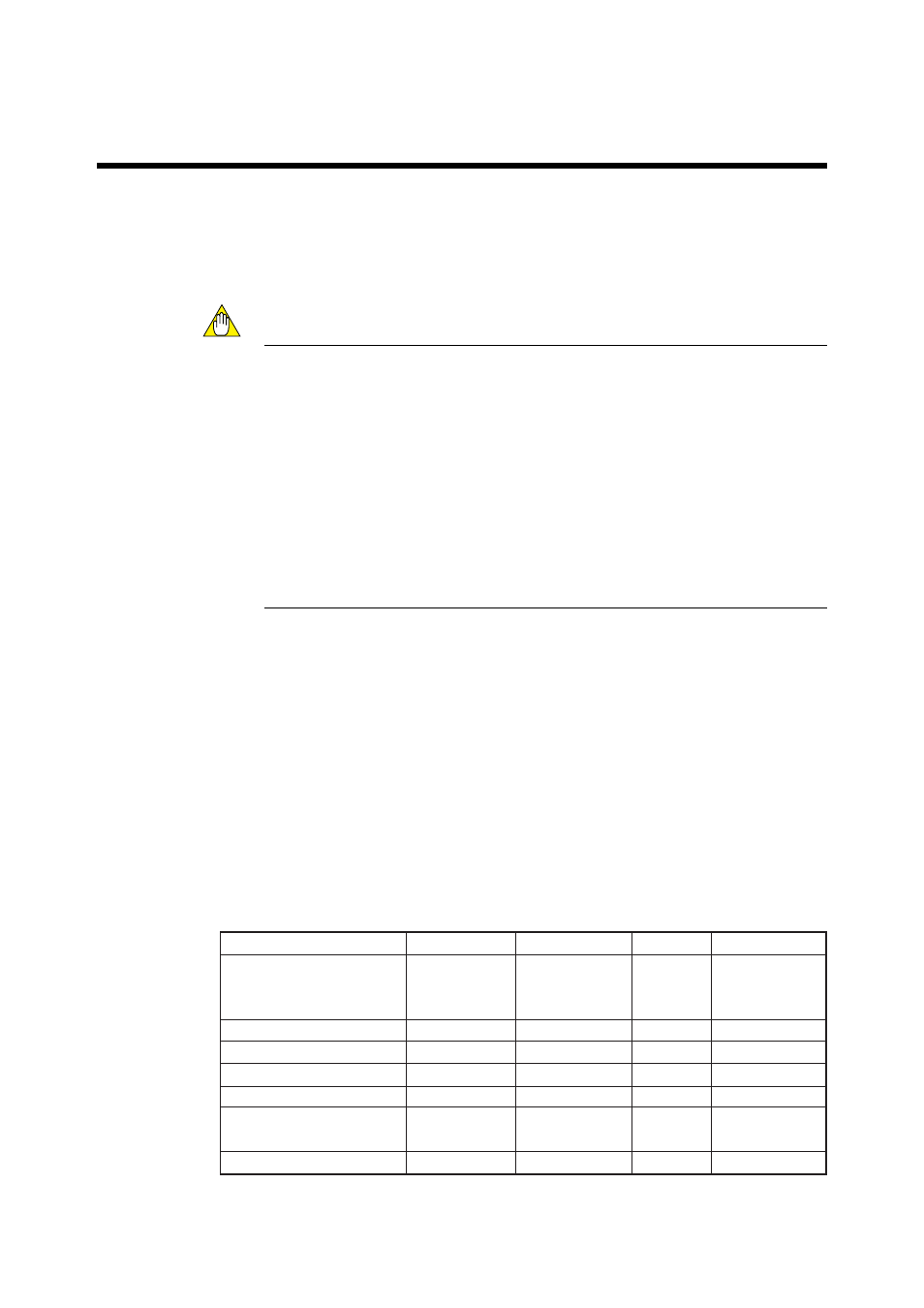
Table 5.1 Cable specifications
T5.1E.EPS
Terminal name of converter
Name
Need for shields
Cable type
Number or wires
CELL+, CELL-
HTR TC+, HTR TC-
CJ+, CJ-
HEATER
L, N,
AO-1+, AO-1-, AO-2+, AO-2-
DO-1, DO-2, DO-3, DO-4
AC-Z, AC-S, AC-C
DI-1, DI-2, DI-C
Converter signal
Converter heater
Power supply
Analog output
Contact output
Automatic
Calibration unit
Contact input
᭺
᭺
CVVS
CVV
CVV
CVVS
CVV
CVV
CVV
6
2
2 or 3 *
2 or 4
2 to 8
3
3
Note *: When the case is used for protective grounding, use a 2-wire cable.