Warning, Figure 4.8 blowback piping – Yokogawa Single Channel Oxygen Analyzer System ZR22/ZR402 User Manual
Page 77
IM 11M13A01-02E
4-8
Instrument air
Pressure regulator
Air Set
Needle
valve
flowmeter
Reference gas
Calibration gas
Check valve
~
Zero gas cylinder
ZR40H Auto Calibration unit
Zirconia Oxygen Analyzer, Detector
ZR402G Converter
Calibration gas
unit case
F1.2E.EPS
ZR22S Separate type Explosionproof
Non-hazardous area
Hazardous area
EXA ZR402G
100 to 240 V AC
Contact input
Analog output, contact output
Digital output (HART)
*2
*1
Signal
(6-core shield cable)
Heater (2-core)
*1: Shield cable;
Use shielded signal cables, and connect the shield to the FG terminal of the
converter.
*2: When a zirconia oxygen analyzer is used, 100% N
2
gas cannot be used as the zero
gas. Use approximately 1% of O
2
gas (N
2
-based).
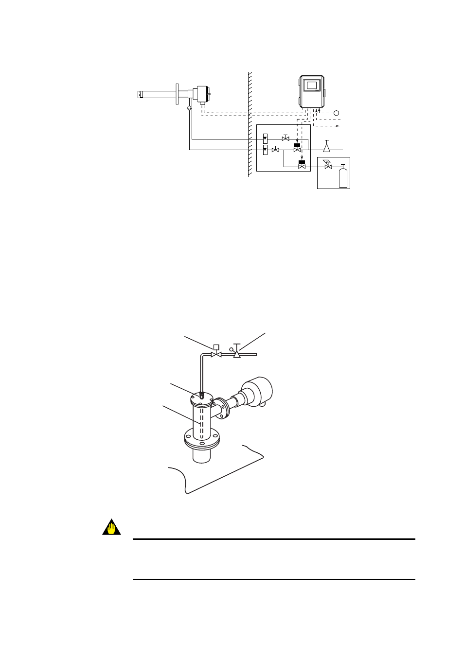
Figure 4.7 Piping for System 2
᭹ Blowback Piping
This piping is required when the blowback function is carried out. The piping described
below provides automatic blowback operation when the “ blowback start “ command is
entered to the converter.
Solenoid valve
Pipe junction
Blow pipe
F4.8E.EPS
Pressure reduction valve
Figure 4.8 Blowback Piping
WARNING
When mounting solenoid valves (e.g. used with options like autocalibration or
blowback) in a hazardous area, then be sure to use explosionproof solenoid valves and
appropriate wiring in explosionproof conduit.