2 wiring, Figure 5.2 wiring connection to the converter – Yokogawa Single Channel Oxygen Analyzer System ZR22/ZR402 User Manual
Page 82
IM 11M13A01-02E
5-3
5. Wiring
5.1.2
Wiring
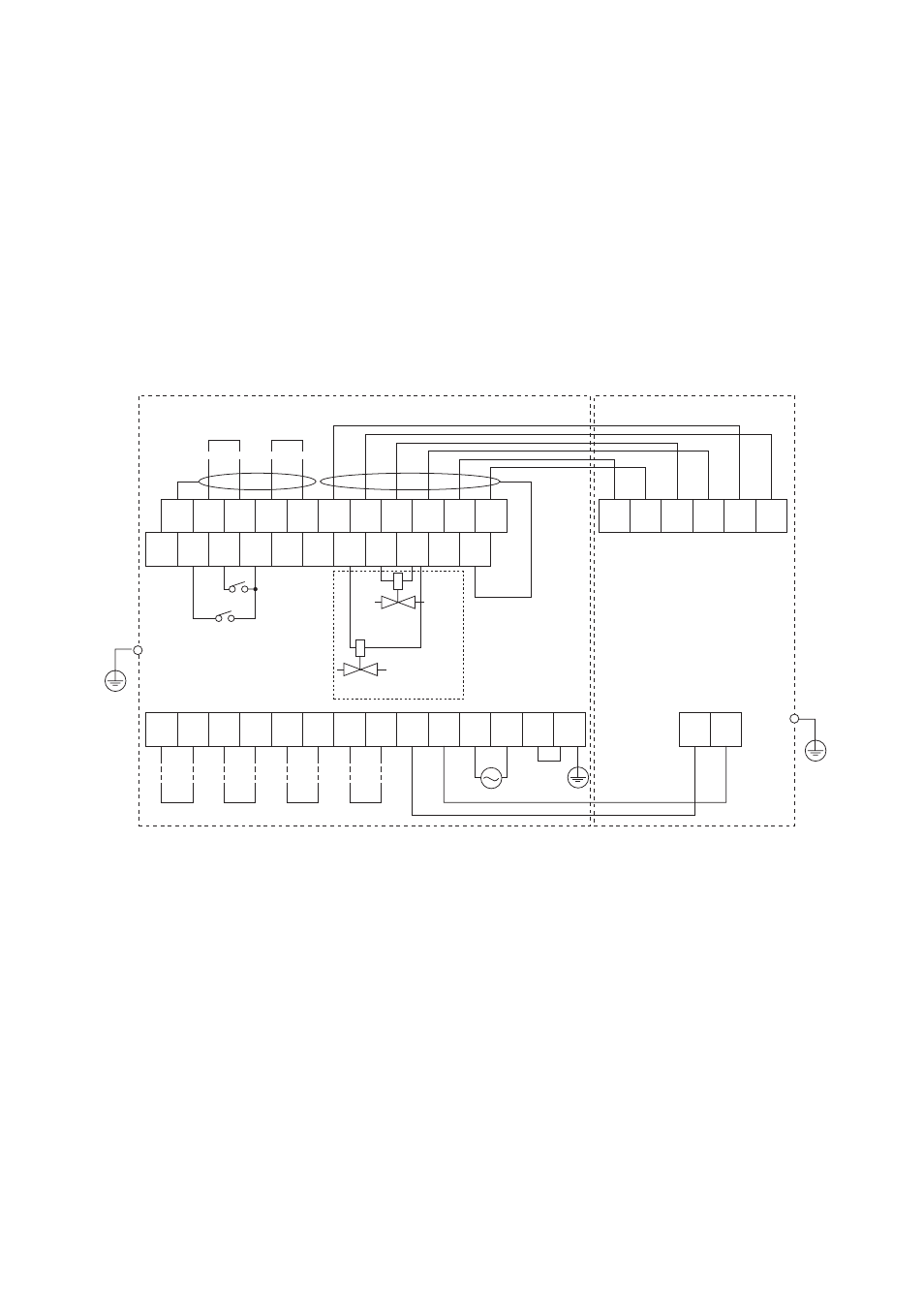
Connect the following wiring to the converter. It requires a maximum of eight wiring
connections as shown below.
(1) Detector output (connects the converter with the detector.)
(2) Detector heater power (connects the converter with the detector.)
(3) Analog output signal
(4) Power and ground
(5) Contact output
(6) Operation of the solenoid valve of automatic calibration unit
(7) Contact input
1
FG
2
AO1
(+)
3
AO1
(-)
4
AO2
(+)
5
AO2
(-)
6
CJ
(+)
7
CJ
(-)
8
TC
(+)
9
TC
(-)
10
CELL
(+)
11
CELL
(-)
12
FG
13
DI-1
14
DI-2
15
DI-C
16
AI
(+)
17
AI
(-)
18
AC-
ZERO
19
AC-
SPAN
20
AC-
COM
21
FG
22
FG
CELL
(+)
CELL
(-)
TC
(+)
TC
(-)
CJ
(+)
CJ
(-)
23
DO-1
24
DO-1
25
DO-2
26
DO-2
27
DO-3
28
DO-3
29
DO-4
30
DO-4
31
HTR
32
HTR
33
L
34
N
35
G
36
FG
HTR
HTR
100-240V AC
50/60 Hz
F5.2E.EPS
Model ZR402G Separate type Zirconia Oxygen Analyzer/
Converter
Model ZR22S Separate type Zirconia
Oxygen Analyzer, Detector
Analog
output 2
Analog
output 1
4-20 mA DC
4-20 mA DC
Digital output
Contact
input 2
Contact input 1
Contact
output 1
Contact
output 2
Contact
output 3
Contact
output 4
Solenoid valve for span gas
for automatic calibration
Solenoid valve for zero gas
for automatic calibration
Flow setting unit
*1
*1
The protective grounding for the converter should be connected to either the protective ground terminal in the equipment or
the ground terminal on the case.
Standard regarding grounding: Ground to earth, ground resistance: 100
⍀
or less.
*1
Figure 5.2 Wiring connection to the converter