Manual calibration – Yokogawa Single Channel Oxygen Analyzer System ZR22/ZR402 User Manual
Page 168
IM 11M13A01-02E
10-17
10. Other Functions
timing for flowing span gas (air) is included in the manual calibration flowchart de-
scribed in Section 10.5.2. For operation of the converter, see Section 7.12, earlier in this
manual.
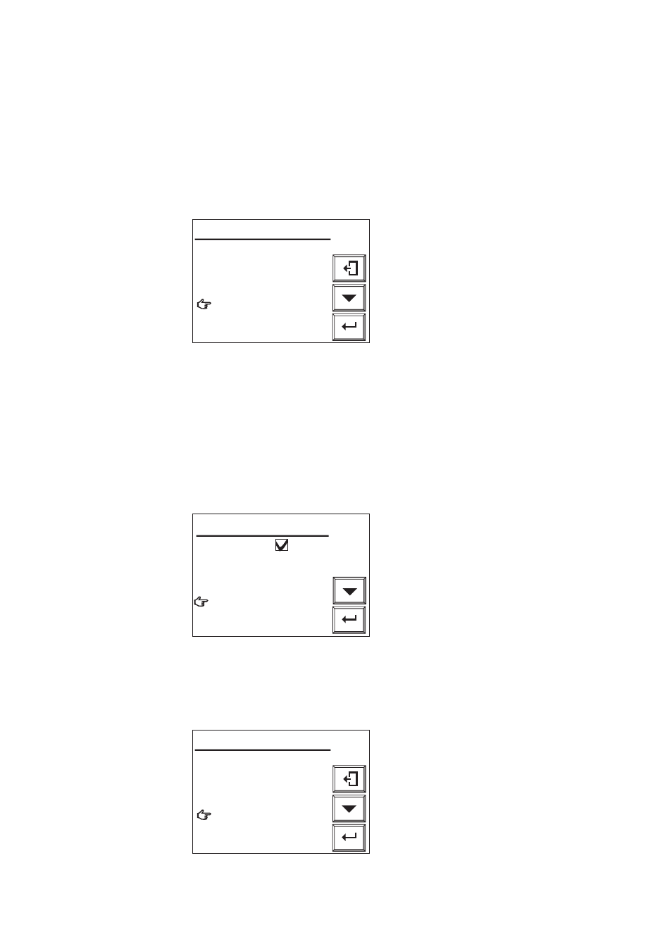
(1) When the message “Open span gas valve” is displayed on the converter display
during calibration, plug the power cord into the power supply socket to start the
pump of the standard gas unit.
Enter
Open span gas valve.
Set flow span gas to
600ml/min.
Valve opened
᭜
Cancel calibration
Manual calibration
F10.15E.EPS
Figure 10.15 Manual Calibration Display
(2) Next, adjust the flow rate to 600
±
60 ml/min using the span gas valve “AIR” (the
flow check ball stops floating on the green line when the valve is slowly opened). To
rotate the valve shaft, loosen the lock nut and turn it using a flat-blade screwdriver.
Turning the valve shaft counterclockwise increases the flow rate.
(3) After adjusting the flow rate, tighten the valve lock nut.
(4) Select Valve opened (to start calibration) from the Manual calibration display shown
in Figure 10.15. Check the Trend graph display to see that the measured value is
stabilized. Then press the [Enter] key. The Manual calibration display shown in
Figure 10.16 appears. Disconnect the power cord to stop the pump.
Enter
Span calibration
Close the span gas valve.
Zero calibration
᭜
End
Manual calibration
F10.16E.EPS
Figure 10.16 Manual Calibration Display
10.17.
Enter
Open zero gas valve.
Set flow span gas to
600ml/min.
Valve opened
᭜
Cancel calibration
Manual calibration
F10.17E.EPS
Figure 10.17 Manual Calibration Display