2 system 2, Figure 1.2 system configuration 2 – Yokogawa Single Channel Oxygen Analyzer System ZR22/ZR402 User Manual
Page 18
IM 11M13A01-02E
1-3
1. Overview
1.1.2
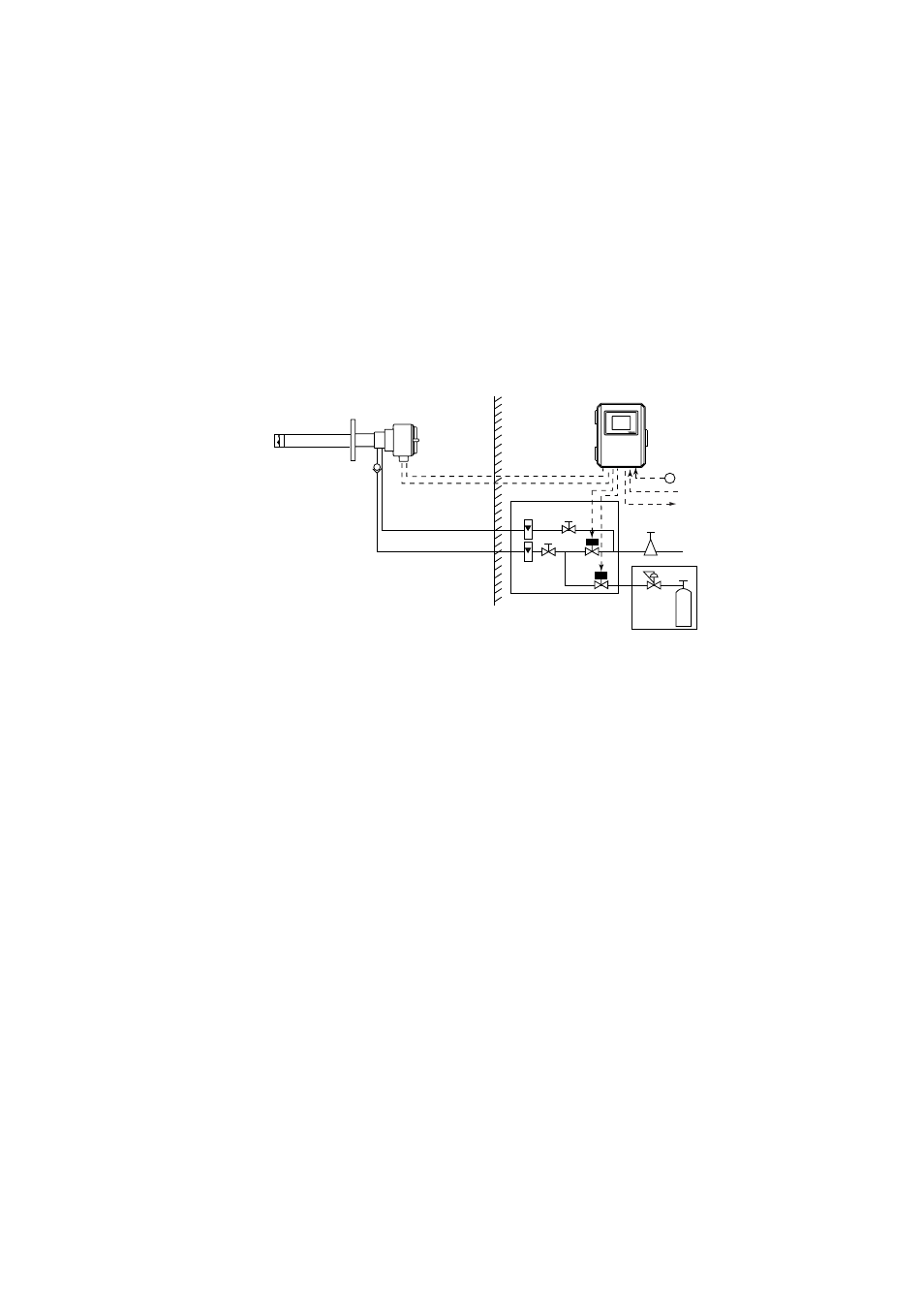
System 2
This example, System 2, represents typical applications in large boilers and heating
furnaces, where there is a need to monitor and control oxygen concentration. The
reference gas and calibration-time span gas are (clean, dry) instrument air. Zero gas is
supplied from a gas cylinder.
System 2 uses the ZR40H autocalibration unit, with auto-switching of the calibration
gas. A “combustible gas detected” contact input turns off power to the heater. There’s
also contact output from the converter that can be used to operate a purge gas valve to
supply air to the sensor.
Instrument air
Pressure regulator
Air Set
Needle
valve
flowmeter
Reference gas
Calibration gas
Check valve
~
Zero gas cylinder
ZR40H Auto Calibration unit
Zirconia Oxygen Analyzer, Detector
ZR402G Converter
Calibration gas
unit case
F1.2E.EPS
ZR22S Separate type Explosionproof
Non-hazardous area
Hazardous area
EXA ZR402G
100 to 240 V AC
Contact input
Analog output, contact output
Digital output (HART)
*2
*1
Signal
(6-core shield cable)
Heater (2-core)
*1: Shield cable;
Use shielded signal cables, and connect the shield to the FG terminal of the
converter.
*2: When a zirconia oxygen analyzer is used, 100% N
2
gas cannot be used as the zero
gas. Use approximately 1% of O
2
gas (N
2
-based).
Figure 1.2 System configuration 2