2 piping for system, 2 piping for system 2 – Yokogawa Single Channel Oxygen Analyzer System ZR22/ZR402 User Manual
Page 76
IM 11M13A01-02E
4-7
4. Piping
4.2
Piping for System 2
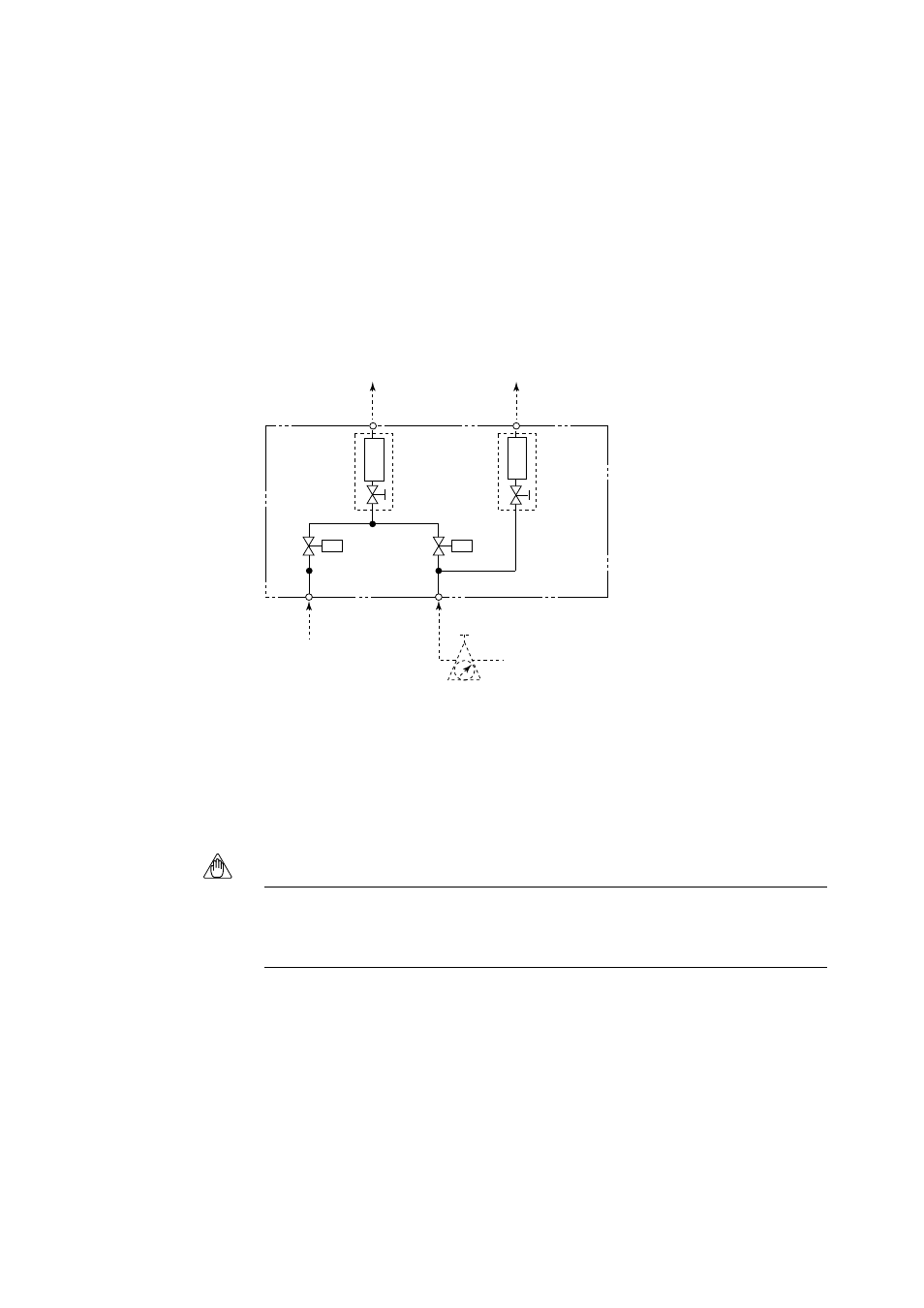
Piping in System 2 is illustrated in Figure 4.7. In System 2, calibration is automated;
however, the piping is basically the same as that of System 1. Refer to Section 4.1.
Adjust secondary pressure of both the air set and the zero gas reducing valve so that
these two pressures are approximately the same. The flow rate of zero and span gases
(normally instrument air) are set by a single needle valve.
After installation and wiring, check the calibration contact output (see Sec. 7.11.2), and
adjust zero gas reducing valve and calibration gas needle valve so that zero gas flow is
within the permitted range. Next check span gas calibration contact output and adjust
air set so that span gas flow is within the permitted range.
CHECK
OUT
ZERO GAS IN
AIR IN
Instrument air Approx.
1.5 l/min.
flow
meter
flow
meter
REF
OUT
*
*
EV1
EV2
Air set
F4.6E.EPS
*: Needle valve comes with flowmeter
Figure 4.6 ZR40H Autcalibration unit piping diagram
If the contact input to the converter is used for the blowback function, prepare blowback
piping according to Section 4.2.
Note
Blowback function means the function to get rid of dust inside a probe in a high-
temperature probe adapter by using compressed air, when a high-temperature detector is
used.