Installation, Removing the screw clamp connectors, Installing the 1/32 din series sd controller – Watlow Series SD PID Profiling Controller User Manual
Page 8: Removing the 1/32 din series sd controller
Wa t l o w S e r i e s S D
•
6
•
C h a p t e r 2 I n s t a l l a n d W i r e
Installing and mounting
requires access to the
back of the panel.
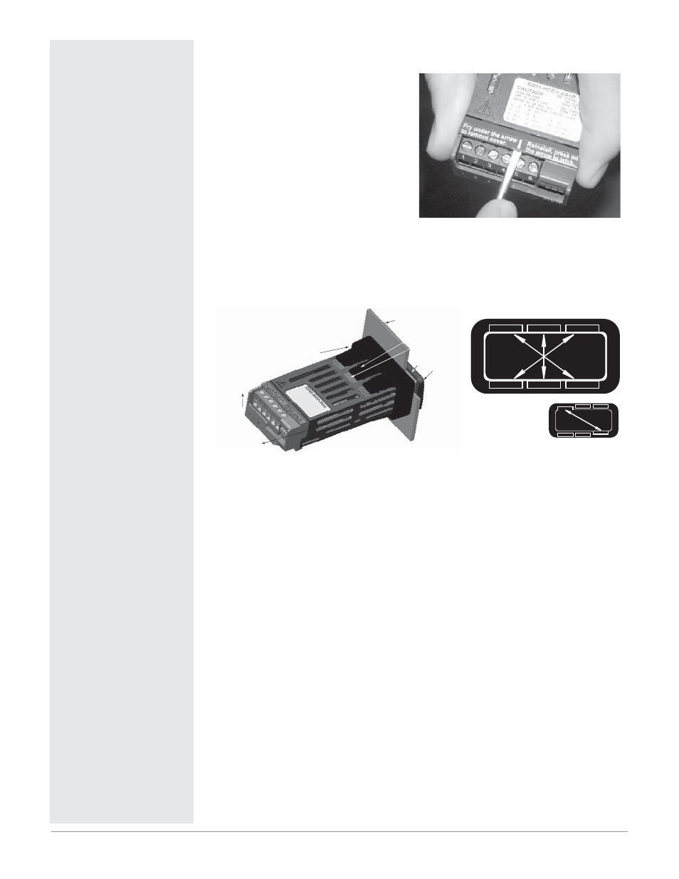
Removing the Screw Clamp Connectors
To prevent component damage when
removing the screw clamp connector,
please follow these steps:
1. Insert a screwdriver in the top of
the spring clamp and lift it up as
shown.
2. Pull out the sensor connector (pins
8 to 11).
3. Lift up the screw clamp connector.
Note: These directions apply to all Series SD
Installation
Installing the 1/32 DIN Series SD Controller
(BTLFU
#F[FM
1BOFM
.PVOUJOH
#SBDLFU
.PVOUJOH5BC
.PVOUJOH3JEHF
$BTF
"SSPXTJOEJDBUFUIF
EJSFDUJPOPGQVMMUP
SFNPWFUIF
DPOOFDUPST
IP65/NEMA 4X
Seal Example
1. Make the panel cutout using the mounting template dimensions in this chapter.
2. Check that the rubber gasket lies in its slot at the back of the bezel. Insert
the controller into the panel cutout.
3. While pressing the bezel firmly against the panel, slide the mounting
bracket over the back of the controller.
4. If the installation does not require an IP65/NEMA 4X seal, slide the brack-
et up to the back of the panel enough to eliminate the spacing between the
gasket and the panel.
For an IP65/NEMA 4X seal, use your thumb to lock the tabs into place
while pressing the controller from side to side. Don’t be afraid to apply
enough pressure to properly install the controller. If you can move the con-
troller back and forth in the cutout, you do not have a proper seal. The tabs
on each side of the bracket have teeth that latch into the ridges.
Each tooth is staggered at a different depth (from the front) so only one of
the tabs on each side is ever locked into the ridges at any time. Either the
two middle tabs or the two tabs diagonal from each other will be engaged.
5. If the matching tabs are not engaged, you do not have an IP65/NEMA 4X
seal. The space between the bezel and panel must be 0 to 0.48 mm (0 to
0.019 in) maximum.
Removing the 1/32 DIN Series SD Controller
1. Remove all the wiring connectors from the back of the controller.
2. Slide a thin, wide tool (putty knife) under all three mounting tabs, on the
top and then the bottom, while pushing forward on the back of the case. Be
ready to support the controller as it slides out of the panel cutout.
Tools required:
Putty knife or equivalent
ç
Caution: Follow the instal-
lation procedure exactly to
guarantee a proper IP65/
NEMA 4X seal. Make sure
the gasket between the
panel and the rim of the
case is not twisted and is
seated properly. Failure to
do so could result in dam-
age to equipment.