Chapter 5: setup page – Watlow Series SD PID Profiling Controller User Manual
Page 28
Wa t l o w S e r i e s S D
•
2 6
•
C h a p t e r 5 S e t u p
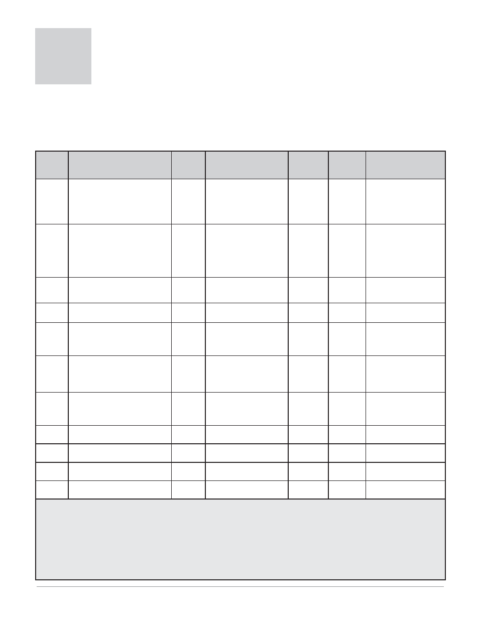
Display
Parameter Name
Description
Settings
Range
(Integer values for Modbus in
parenthesis.)
Default
Modbus*
(less 40,001
offset)
Read/Write
Appears if:
[`SEn]
[ SEn]
Sensor Type
Set the analog sensor type.
[``tc] (0)
[`rtd] (1)
[`MA] (2)
[uolt] (3)
[~mu] (5)
[``tc] (0)
70 R/W
Always active.
[`Lin]
[ Lin]
Thermocouple Linearization
Set the analog input thermo-
couple linearization.
[```J] J (0) [```D] D (6)
[```H] K (1) [Pt11] PTII (7)
[```t] T (2) [```R] R (8)
[```E] E (3) [```S] S (9)
[```n] N (4) [```B] B (10)
[```C] C (5)
[tc`J] (0)
71 R/W
[`Sen] is set to [``tc].
[`C-F]
[ C-F]
Temperature Units
Set the temperature units for
thermocouple and RTD inputs.
[```F] Fahrenheit (0)
[```C] Celsius (1)
[```F] (0)
40 R/W
[`Sen] is set to [``tc]
or
[`rtd].
Temperature Units via Serial
Comms
Fahrenheit (0)
Celsius (1)
(0)
18 R/W
[`Sen] is set to [``tc]
or
[`rtd].
[S;deC]
[S.dEC]
Temperature Decimal Places
Set the decimal places for the
displayed input value for ther-
mocouple and RTD types.
[```0] (0)
[``0;0] (1)
[```0] (0)
41 R/W
[`Sen] is set to [``tc]
or
[`rtd].
[P;dEC]
[P.dEC]
Process Decimal Places
Set the decimal places for the
displayed input value for process
types.
[```0] (0)
[``0;0] (1)
[`0;00] (2)
[0;000] (3)
[```0] (0)
42 R/W
[`Sen] is set to [`mA],
[uoLt] or [`mu].
[IS;En]
[IS.En]
INFOSENSE™
Enable the sensor feature, which
synchronizes the controller with
a Watlow sensor.
[``no] (0)
[`Yes] (1)
[``no] (0)
91 R/W
Always active.
[IS;P1]
[IS.P1]
INFOSENSE™ 1
Set sensor point 1 code.
0 to 999 (0 to 999)
500
92 R/W
[IS;En] is set to [`yes].
[IS;P2]
[IS.P2]
INFOSENSE™ 2
Set sensor point 2 code.
0 to 999 (0 to 999)
500
93 R/W
[IS;En] is set to [`yes].
[IS;P3]
[IS.P3]
INFOSENSE™ 3
Set sensor point 3 code.
0 to 999 (0 to 999)
500
94 R/W
[IS;En] is set to [`yes].
[IS;P4]
[IS.P4]
INFOSENSE™ 4
Set sensor point 4 code.
0 to 999 (0 to 999)
500
95 R/W
[IS;En] is set to [`yes].
Note: Some values will be rounded off to fit in the four-character display. Full values can be read with Modbus. All temperature pa-
rameters through Modbus are in °F, by default. Writing to register 18 will toggle between °F and °C.
* Low register numbers contain the two higher bytes; high register numbers contain the two lower bytes of the four-byte integer.
Decimal precision is implied at three decimal places unless otherwise noted.
** Static set point version only (SD_C-_ _ _ _- _ _ _ _ ).
*** Profiling version only (SD_R-_ _ _ _- _ _ _ _ ).
5
Chapter 5: Setup Page
To go to the Setup Page, press both the Up ¿ and Down ¯ keys for three seconds from the Home Page. [`SEt]
will appear in the upper display and
[PAgE] will appear in the lower display.
• Press the Advance Key ‰ to move through the parameter prompts.
• Press the Up ¿ or Down ¯ key to change the parameter value.
• Press the Infinity Key ˆ at any time to return to the Home Page display.