Retransmit, Communications, Alarm hysteresis – Watlow Series SD PID Profiling Controller User Manual
Page 73: Alarm latching, Alarm silencing, Overview
Wa t l o w S e r i e s S D
•
7 1
•
C h a p t e r 1 2 F e a t u r e s
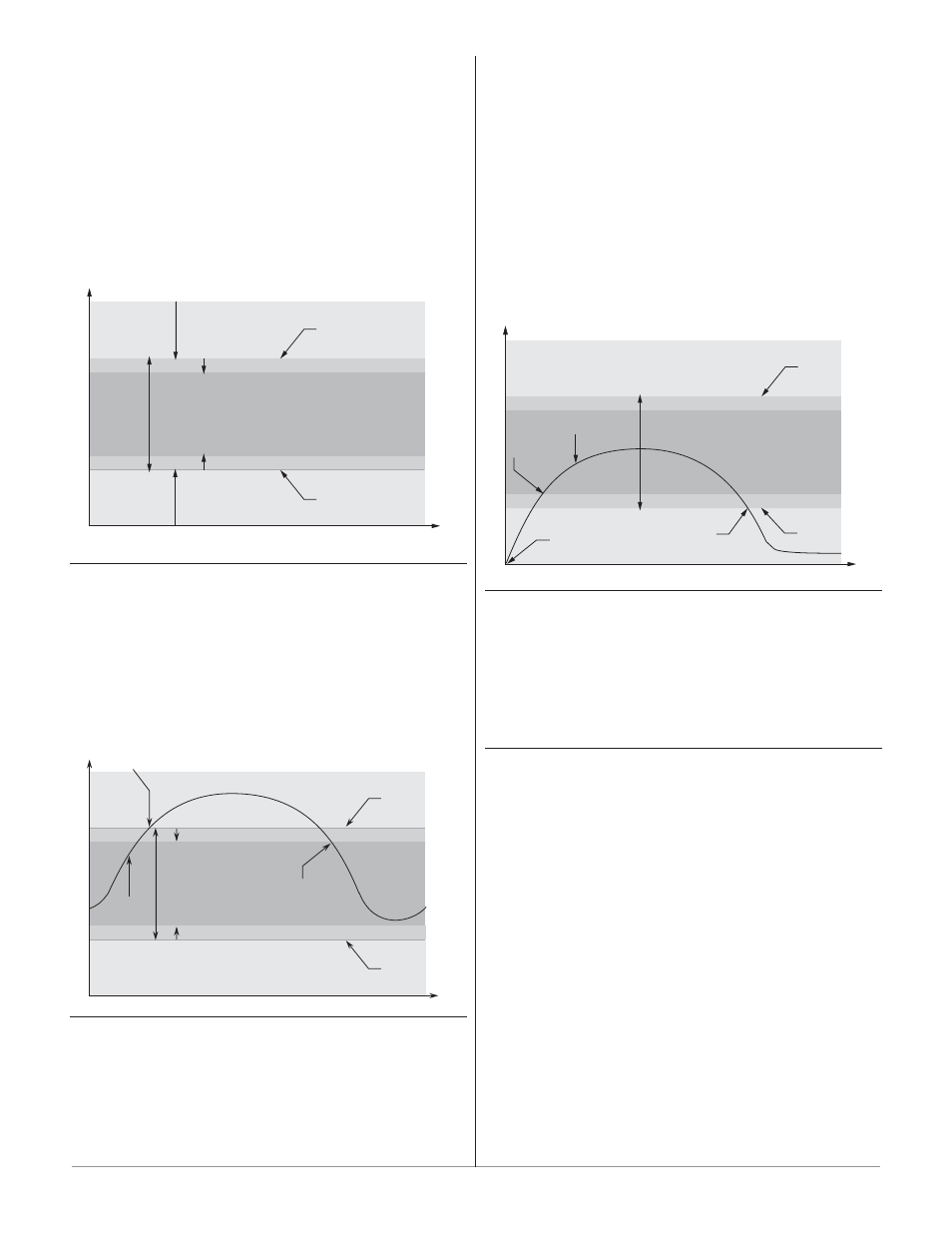
Alarm Hysteresis
An alarm state is triggered when the process value
reaches the alarm high or alarm low set point. Alarm
hysteresis defines how far the process must return into
the normal operating range before the alarm can be
cleared.
Alarm hysteresis is a zone inside each alarm set
point. This zone is defined by adding the hysteresis value
to the alarm low set point or subtracting the hysteresis
value from the alarm high set point.
View or change alarm hysteresis Alarm 1, 2, or 3 Hys-
teresis,
[hyS1], [hyS2] or [hyS3] (Setup Page).
Normal Operating Range
Low Side Alarm Range
High Side Alarm Range
Alarm High Set Point
Alarm Low Set Point
Time
Temperature
Alarm Hysteresis
Alarm Hysteresis
Alarm Latching
A latched alarm will remain active after the alarm
condition has passed. To clear a latched alarm, press the
Infinity Key ˆ. It can only be deactivated by the user. An
alarm that is not latched (self-clearing) will deactivate
automatically when the alarm condition has passed.
Turn alarm latching on or off with Alarm 1, 2, or 3
Latching
[LAt1], [LAt2] or [LAt3] (Setup Page).
Normal Operating Range
Alarm High
Set Point
Time
Temperature
Alarm Low
Set Point
The alarm state continues until the
temperature drops to the Alarm High
Set Point minus the hysteresis. A
latching alarm could be turned off by
the operator at this point. A non-
latching alarm would turn off
automatically.
The alarm state begins when the temperature
reaches the Alarm High Set Point
Process
Temperature
Alarm Hysteresis
Alarm Silencing
Alarm silencing has two uses:
1. It is often used to allow a system to warm up after
it has been started up. With alarm silencing on, an
alarm is not triggered when the process tempera-
ture is initially lower than the alarm low set point.
The process temperature has to enter the normal
operating range beyond the hysteresis zone to acti-
vate the alarm function.
2. Alarm silencing also allows the operator to dis-
able the alarm output while the controller is in an
alarm state. The process temperature has to enter
the normal operating range beyond the hysteresis
zone to activate the alarm output function.
If the Series SD has an output that is functioning as a
deviation alarm, the alarm is blocked when the set point
is changed, until the process value re-enters the normal
operating range.
Turn alarm silencing on or off with Alarm 1, 2, or 3 Si-
lencing
[SiL1], [SiL2] or
[
SiL3] (Setup Page).
Normal Operating Range
Alarm
enabled
here
Alarm
triggered
here
Startup,
Alarm
disabled
Time
Temperature
Alarm High
Set Point
Alarm Low
Set Point
Process
Temperature
Hysteresis
Hysteresis
Retransmit
The retransmit feature allows a process output to
provide an analog signal that represents the set point or
actual process value. The signal may serve as a remote
set point for another controller or as an input for a chart
recorder to document system performance over time. Any
process output can be configured as a retransmit output.
Communications
Overview
A Series SD controller can also be programmed and
monitored by connecting it with a personal computer or
programmable logic controller (PLC) via serial communi-
cations. To do this it must be equipped with an EIA/TIA-
485 (SD_ _ - _ _ U_ - _ _ _ _) communications option for
Output 2. Your PC or PLC must have available an EIA/
TIA-485 interface or use an EIA/TIA-232 to EIA/TIA-485
converter. See “Selecting an EIA/TIA-232 to EIA/TIA-485
converter” in the Install and Wire chapter. The EIA/TIA-
485 option directly supports communication with up to
32 devices on a network or up to 247 devices using a 485
repeater.
Basic communications settings must first be config-
ured on the controller in the Setup Page. Match the Baud
Rate
[bAud] to that of the computer and select a unique
Address
[Addr] for each Series SD.
To view or change controller settings with a personal
computer, you need to run software that uses the Modbus