Watlow Series SD PID Profiling Controller User Manual
Page 41
Wa t l o w S e r i e s S D
•
3 9
•
C h a p t e r 6 O p e r a t i o n s
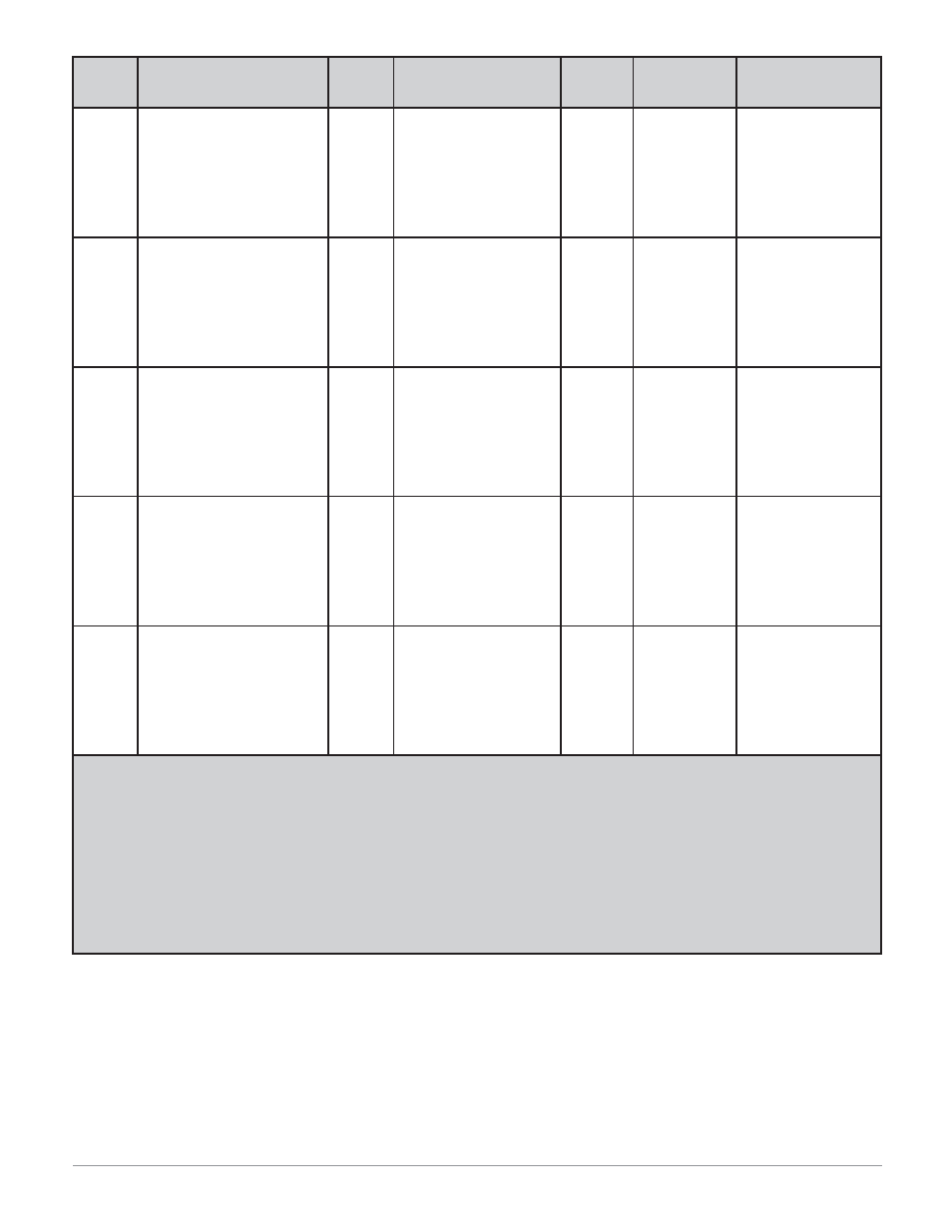
Display
Parameter name
Description
Settings
Range
Default
Modbus*
(less 40,001 offset)
Read/Write
Appears if"
[A1;Lo]
[A1.Lo]
Alarm 1 Low
Set the low alarm set point.
Deviation: -1999 to 0
(-1999000 to 0000)
Process: range of sensor, if
[`SEN] is set to [``tc]
or
[`rtd]
-1999 to 9999 if
[`SEN] is
set to
[`Ma] or [uolt].
(-1999000 to 9999000)
-999 (dev)
32 (pro)
*98, 99 R/W
(dev)
*102, 103 R/W
(pro)
[Ot`1] is set to
[dE;AL] or [Pr;AL]
[A2;hi]
[A2.hi]
Alarm 2 High
Set the high alarm set point.
Deviation: 0 to 9999 (0000
to 9999000)
Process: range of sensor, if
[`SEN] is set to [``tc]
or
[`rtd]
-1999 to 9999 if
[`SEN] is
set to
[`Ma] or [uolt].
(-1999000 to 9999000)
999 (dev)
1500 (pro)
*115, 116 R/W
(dev)
*119, 120 R/W
(pro)
[Ot`2] is set to
[dE;AL] or [Pr;AL].
[A2;Lo]
[A2.Lo]
Alarm 2 Low
Set the low alarm set point.
Deviation: -1999 to 0
(-1999000 to 0000)
Process: range of sensor, if
[`SEN] is set to [``tc]
or
[`rtd]
-1999 to 9999 if
[`SEN] is
set to
[`Ma] or [uolt].
(-1999000 to 9999000)
-999 (dev)
32 (pro)
*113, 114 R/W
(dev)
*117, 118 R/W
(pro)
[Ot`2] is set to
[dE;AL] or [Pr;AL].
[A3;hi]
[A3.hi]
Alarm 3 High
Set the high alarm set point.
Deviation: 0 to 9999 (0000
to 9999000)
Process: range of sensor, if
[`SEN] is set to [``tc]
or
[`rtd]
-1999 to 9999 if
[`SEN] is
set to
[`Ma] or [uolt].
(-1999000 to 9999000)
999 (dev)
1500 (pro)
*130, 131 R/W
(dev)
*134, 135 R/W
(pro)
[Ot`3] is set to
[dE;AL] or [Pr;AL].
[A3;Lo]
[A3.Lo]
Alarm 3 Low
Set the low alarm set point.
Deviation: -1999 to 0
(-1999000 to 0000)
Process: range of sensor, if
[`SEN] is set to [``tc]
or
[`rtd]
-1999 to 9999 if
[`SEN] is
set to
[`Ma] or [uolt].
(-1999000 to 9999000)
-999 (dev)
32 (pro)
*128, 129 R/W
(dev)
*132, 133 R/W
(pro)
[Ot`3] is set to
[dE;AL] or [Pr;AL].
Note: Parameters appear in the Operations Page only if activated from the programming page. See page 22 for Operations Page defaults.
Note: Some values will be rounded off to fit in the four-character display. Full values can be read with Modbus. All temperature param-
eters through Modbus are in °F, by default.
* Low register numbers contain the two higher bytes; high register numbers contain the two lower bytes of the four-byte integer. Decimal
precision is implied at three decimal places unless otherwise noted.
** Static set point version only (SD_C-_ _ _ _- _ _ _ _ ).
*** Profiling version only (SD_R-_ _ _ _- _ _ _ _ ).
**** This value multiplied by 100 equals the percent power.