Troubleshooting – Watlow Series SD PID Profiling Controller User Manual
Page 76
Wa t l o w S e r i e s S D
•
7 4
•
C h a p t e r 1 O v e r v i e w
Wa t l o w S e r i e s S D
•
7 4
•
C h a p t e r 1 2 F e a t u r e s
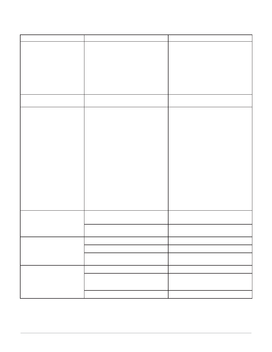
Indication
Probable Cause
Corrective Action
No power.
Controller appears dead.
No display indication in either
window.
Power to unit may be off.
Fuse may be blown.
Breaker may be tripped.
Safety interlock door switch, etc. may be ac-
tivated.
Separate system limit control may be
latched.
Wiring may be open.
Input power may be incorrect.
Check switches, fuses, breakers, interlocks,
limit devices, connectors, etc. for energized
condition and proper connection.
Measure power upstream for required level.
Verify supply power requirements using the
part number.
Check wire size.
Check for bad connections.
One of the displays is not on.
Active Displays
[`dSP]
(Setup) is not set to
[`nor]
.
Verify that
[`dSP]
is at the desired setting.
Cannot establish serial data com-
munications with the controller.
Address parameter may be incorrectly set.
Baud rate parameter may be incorrectly set.
Unit-to-unit daisy chain may be discon-
nected.
Communications wiring may be reversed,
shorted or open.
EIA-485 converter box may be incorrectly
wired.
Computer’s COM port may be incorrectly set
up.
Communications software setup or address
may be incorrect.
PC software’s protocol or parity may be
wrong. Parity should be 8, n, 1.
Application software is not working properly.
May need termination, pull-up and pull-down
resistors.
Check Setup Page and set to correct address.
Check Setup Page and set to correct baud
rate.
Look for a break in the daisy chain.
Verify correct connections and test wiring
paths.
Check converter box wiring and its documen-
tation.
Reconfigure computer’s COM port setup and
verify that communications are ok.
Check the communication card documenta-
tion for settable variables and operational
testing.
Restart PC software and check for settings
agreement. Verify the COM bus is active.
Verify operation with Watlow communica-
tions tool available at www.watlow.com.
Add termination resistors for EIA/TIA-485
(see Install and Wire chapter).
Cannot establish infrared com-
munications link.
Optical transceiver path obstructed.
Infrared device too far away.
Hold the infrared device within range and
angle of view to the controller.
Infrared device software settings do not
match controller’s infrared settings.
Verify infrared settings.
Output signal is on when it
should not be.
Output wiring is incorrect.
Verify the output wiring.
Output parameters are set incorrectly.
Verify the output parameter settings.
DC voltage applied to output option “K”
(solid-state relay output).
Solid-state relay option can be used with al-
ternating current (ac) voltage only.
Output signal is not on when it
should be.
Output wiring is incorrect.
Verify the output wiring.
For solid-state relay (option “K”) and me-
chanical relay (option “E” or “J”), power must
be applied.
Verify that power is applied to the output.
The output simply acts as a switch.
Output parameters are set incorrectly.
Verify the output parameter settings.
Troubleshooting