Ez-zone rm-access module - system diagram, Watlow ez-zone, Rma module – Watlow EZ-ZONE RMA Modul User Manual
Page 9: Chapter 1 overview
Watlow EZ-ZONE
®
RMA Module
•
6
•
Chapter 1 Overview
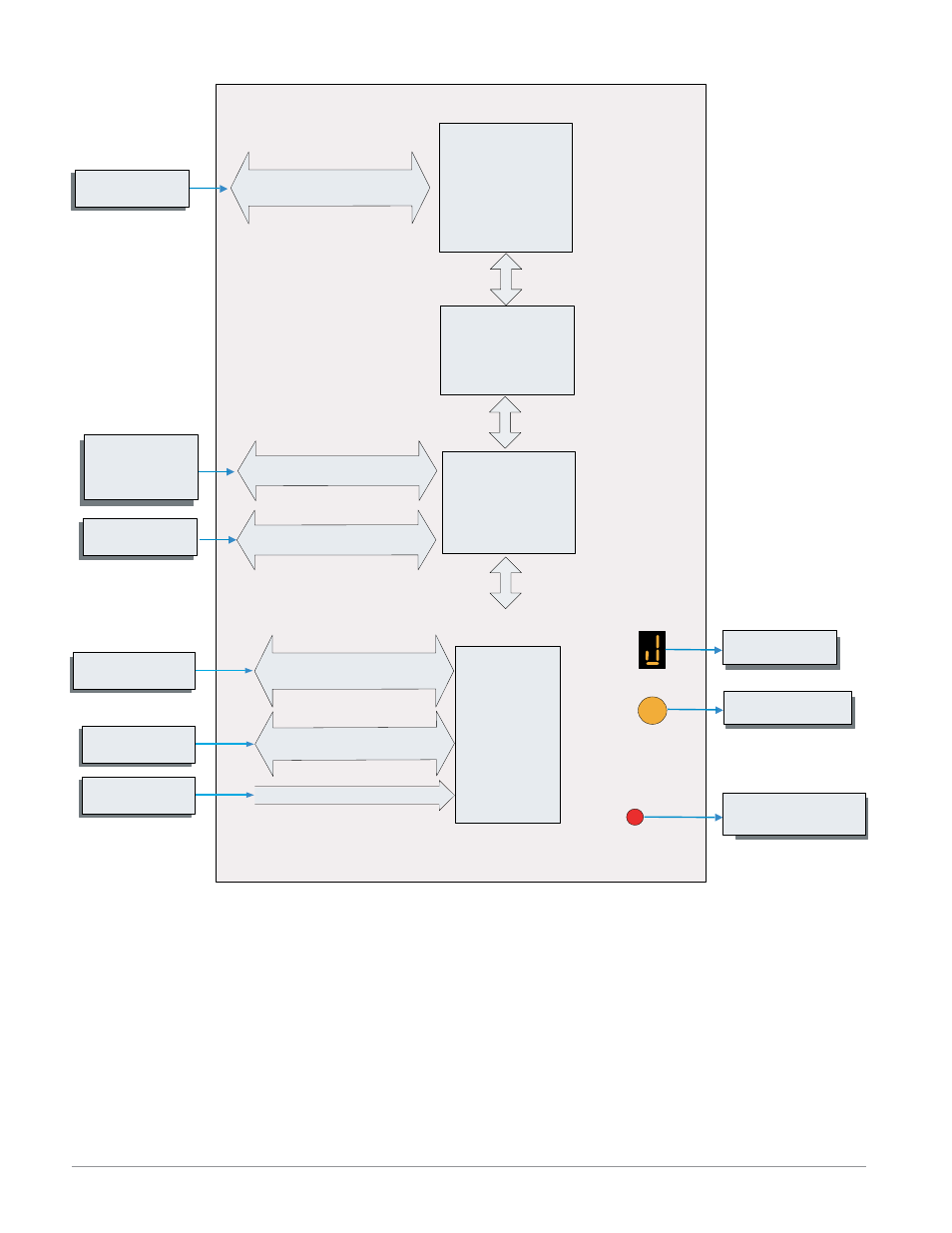
EZ-ZONE RM-Access Module - System Diagram
Zone Selection
Button
S
Protocol of Choice
- EtherNet/IP
- DeviceNet
- Modbus RTU
- Modbus TCP
- Profibus DP
Slot E
(optional)
EIA - 232/485 or Ethernet
Fieldbus Protocol
PLC, PC or OIT
Profile Ramp & Soak
Battery Backup &
Real Time Clock
(optional)
Storage Device
(Configuration,
Memory and Data
Logging)
PC
Micro SD
Memory Socket
Auto Configuration,
Backup, USB Port
and Data Logging
Slot D
(optional)
Mini Type B USB Port v1.1
(as device only)
EIA - 485 Communications
Standard Bus
Inter-module Bus
RUI, PC
Other RM Modules
Power Supply
Standard Bus
Zone 1 - 17
Supervisory &
Power Board
Slot C
20.4 to 30.8 Vac or Vdc
Push to select Zone
Address
Indicates Zone
Address
Indicates Standard Bus
communications activity
Output
Function
Input
Function
- 12LS Controller (111 pages)
- 8LS Controller (140 pages)
- 8PID Controller (55 pages)
- Addendum to EZwarePlus (50 pages)
- ANASCAN (62 pages)
- ANASOFT (95 pages)
- ANAWIN 2 (154 pages)
- ANAWIN 3 (23 pages)
- Calibrating Watlow Series 988 Family Process Controls (19 pages)
- CAS (98 pages)
- CAS200 (124 pages)
- CLS (180 pages)
- CLS200 (251 pages)
- CLS200, MLS300 and CAS200 (92 pages)
- Control Console (12 pages)
- CPC400 (230 pages)
- DIN-A-MITE Style A (9 pages)
- DIN-A-MITE Style B (14 pages)
- DIN-A-MITE Style C (22 pages)
- DIN-A-MITE Style D (9 pages)
- DIN-Mount Adapter Instruction Sheet, Rev A (1 page)
- Dual DAC (4 pages)
- EM Gateway (28 pages)
- E-Safe Hybrid Relay Rev B (4 pages)
- E-SAFE II Hybrid Power Switch (4 pages)
- EZwarePlus Programming (264 pages)
- EZ-ZONE PM (111 pages)
- EZ-ZONE PM PID (125 pages)
- EZ-ZONE PM Express Limit (34 pages)
- EZ-ZONE PM Express (35 pages)
- EZ-ZONE PM Integrated Controller (181 pages)
- EZ-ZONE RM Limit Module Rev C (127 pages)
- EZ-ZONE RMC (236 pages)
- EZ-ZONE RME (124 pages)
- EZ-ZONE RMH (161 pages)
- EZ-ZONE RUI/Gateway (62 pages)
- EZ-ZONE RM-Scanner-Modul (140 pages)
- EZ-ZONE ST (97 pages)
- F4 External Event Board - Rev.B (2 pages)
- HG Series Mercury Displacement Relay (6 pages)
- LogicPro (296 pages)
- Mercury Relay or MDR Retrofit (13 pages)
- MICRODIN (24 pages)
- MICRODIN (106 pages)